NAPCO Gemini C-Series Control Panel Installation Instructions--Volume 2
Page 8 Installation Instructions, Volume 2
NAC SYNCHRONIZATION RULES
The UL 864 9
th
edition standard includes the requirement
that all visible notification appliances in the same field of
view and all audible notification appliances in the same notifi-
cation zone operate in a synchronized manner.
The Gemini C-Series control panels and NAC extenders
comply with this standard with three different methods that
must be understood before a final installation method is se-
lected.
DEFINITIONS
1. NAC Circuit
: One of 4 possible outputs on either the
GEMC-NACXX or GEMC-XXXMB motherboard. Each
NAC circuit can deliver UP TO 2.0A.
2. Notification Zone
: A common evacuation area. Multiple
circuits can be in a zone.
3. Field of View: All the strobes that can be seen by an indi-
vidual at any point WITHIN the protected premises.
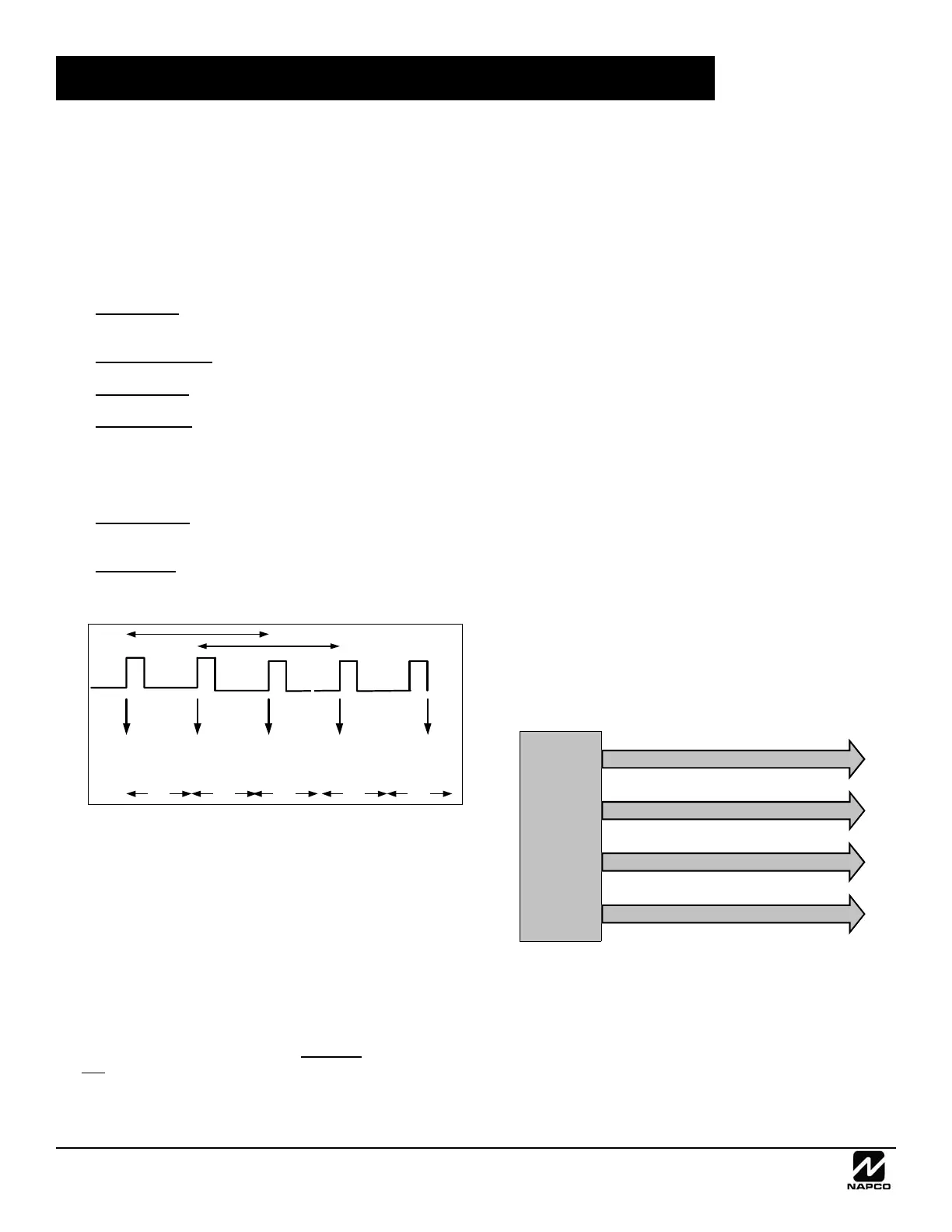
4. Sync Pattern:
The GEMC-NACXX or GEMC-XXXMB
have two sync patterns: S1 and S2. A synchronized NAC
output must be assigned to S1 or S2. The two sync pat-
terns are ½ second apart as shown in Fig 1 below. S2 is
referred to as the "offset" since it is offset ½ second from
S1.
5. Synch Group:
A collection of NAC circuits on the GEMC-
XXXMB and one or multiple GEMC-NACXX's sharing the
same sync pattern.
6. Sync Input:
An input connection that allows a GEMC-
NACXX to synchronize its sync patterns to the main panel
or to another GEMC-NACXX.
Method 1 (Standard Temporal)
Most installations only require synchronized strobes and syn-
chronized temporal sounding appliances. The easiest
method used to comply with this requirement is to use either
the compatible Wheelock or System Sensor "Smart" devices,
as listed in the GEMC-XXXMB installation instructions
(WI1653). When these are used, the strobes and horns can
share the same NAC wires, reducing the number, length and
complexity of wire runs. The following rules apply:
Rule 1: "Smart" devices must either be System Sensor or
Wheelock, but both can not be used in the same system.
Rule 2: The total current from the combined NAC circuits on
one
GEMC-XXXMB or NAC7L/7S sharing the same sync
pattern cannot exceed 4A. [Example: NAC A and B synched
to S1 draw 4A and NAC C and D are offset using S2 for a
total of 2.5A].
Rule 3: All notification appliances in the same field of view
must use the same sync pattern.
The maximum current draw from "Smart" (Synchronized)
circuits on either the GEMC-XXXMB or GEMC-NACXX can
not exceed 4A (non-synchronized NAC circuits can draw a
maximum 6.5A from the NAC's) if all visible notification appli-
ances are in the same field of view and all audible notifica-
tion appliances are in the same notification zone.
However, if there are two or more Synch Groups, then the
full 6.5A maximum alarm current can be utilized by wiring
one group to the first two NAC's, wiring the second group to
the third and fourth NAC's and programming/configuring the
GEMC-XXXMB / GEMC-NACXX for "NAC offset". This will
cause the 2 pairs of NAC circuits to activate the strobes and
horns ½ a second apart. Note: Each NAC maximum cur-
rent is 2A. Warning: Strobes not within the same sync
group may never be within the same field of view.
Rule 4: If a group of notification appliances in the same field
of view and all audible notification appliances in the same
notification zone require more than 4A, an additional GEMC-
NACXX must be used and synchronized using a dedicated
NAC circuit from a master GEMC-XXXMB or GEMC-NACXX
wired to the INPUT 1 of the slave GEMC-NACXX.
Rule 5: In large systems with multiple groups of notification
appliances in the same field of view and all audible notifica-
tion appliances in the same notification zone, the maximum
alarm current of each GEMC-XXXMB / GEMC-NACXX can
be utilized by programming / configuring the GEMC-
XXXMB / GEMC-NACXX for "NAC offset" and grouping all
non-offset outputs together and offset outputs together.
Small System – No NAC7L/7S Extender – Long Wire Runs
In this example, NAC A, B, C and D are one Sync Group us-
ing S1 supplying 4A on four circuits, with each circuit supply-
ing 1A. This allows the longest wire runs but trades off
against output power by limiting to 4A.
Small System – No NAC7L/7S Extender – Normal Runs
In this example, NAC A and B are one Sync Group using S1
supplying 4A and NAC C and D are a Sync Group using S2,
offset from S1, supplying 2.5A:
NAC SYNCHRONIZATION RULES
v
Pattern
S1
Fires
Pattern
S2
Fires
Pattern
S1
Fires
Pattern
S2
Fires
0.5 Sec
Pattern
S1
Fires
0.5 Sec0.5 Sec0.5 Sec0.5 Sec
FIG. 1: TWO SYNC PATTERNS ARE ½ SECOND APART
GEMC-
XXXMB
NAC A - Sync S1 - 1 Amp
NAC B - Sync S1 - 1 Amp
NAC C - Sync S1 - 1 Amp
NAC D - Sync S1 - 1 Amp
 Loading...