14 NAPCO StarLink Fire: Getting Started Guide
The following summarizes the minimum required NOC programming (hƩp://NapcoNOC.com) and system wiring for reporƟng alarm and trouble events trig-
gered by the relays of a Fire Alarm Control Panel (FACP). Check the installaƟon and programming instrucƟons for addiƟonal wiring and programming opƟons.
Be sure all items in the following checklist are performed:
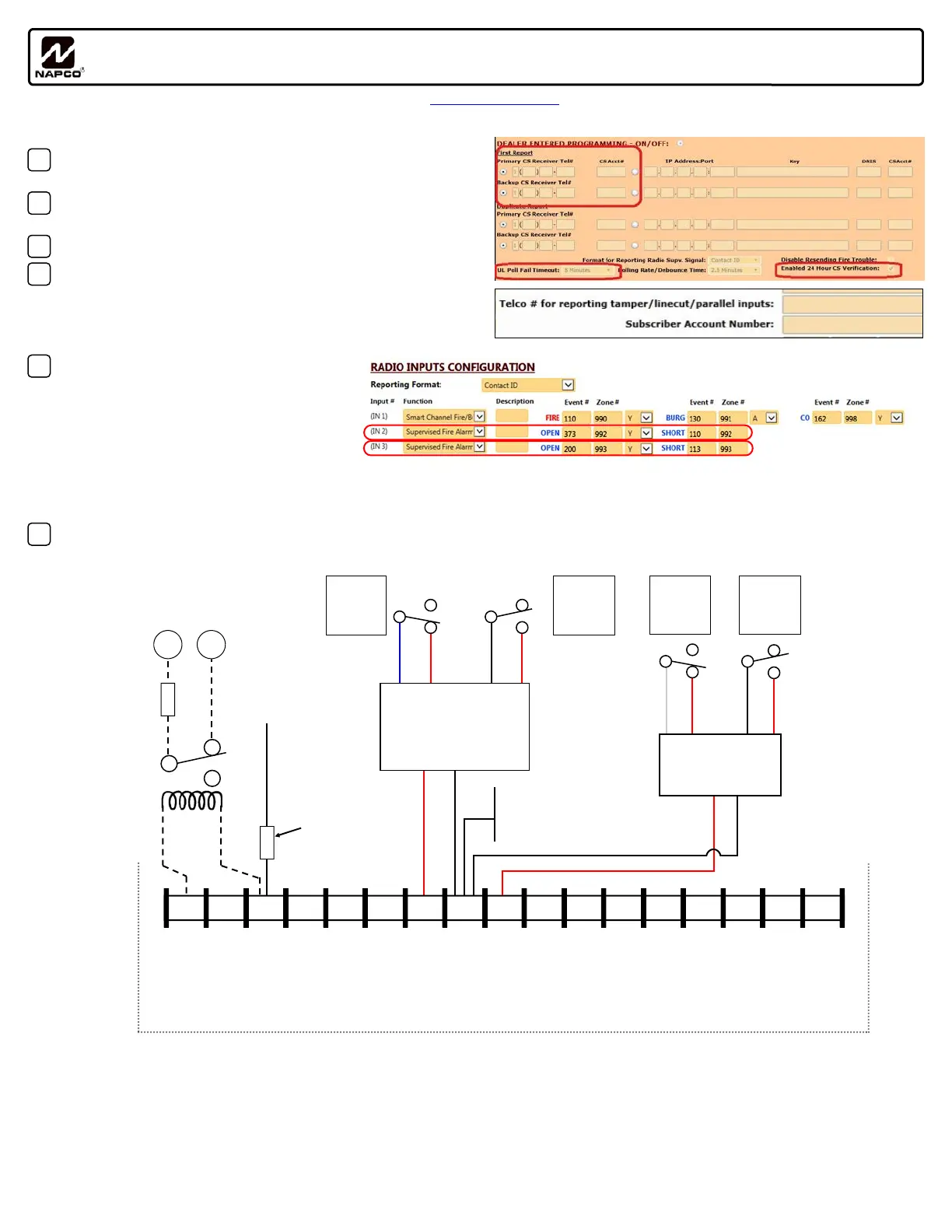
1. Central StaƟon Receiver Telephone numbers are programmed in the
"DealerEnteredProgramming" secƟon (see image at right):
2. ULPollFailTimeout is set (200 seconds NFPA 2007 service plan; 5 min.
for NFPA 2010 plan; 60 min. for NFPA 2013 plan or 24hr backup only):
3. Set CS Test Timer to 6hr or 24hr.
4. The central staƟon receiver telephone number ("Telco # for repor ng
tamper/linecut/parallel inputs") and account number ("Subscriber
AccountNumber") are programmed in the Adva nced tab:
Note: The central staƟon receiver telephone number and account
number must be manually entered.
5. Input 2 (IN2) and Input 3 (IN3) is set for Super-
visedFireAlarm/FireTrouble, and the desired
event number and zone numbers are pro-
grammed for Fire Alarm and Fire Trouble (also
programmed for other trouble condiƟons as
required by the local AHJ). Upon loss of power
or trouble, the FACP N/C relay must change
state from closed to open; see wiring diagram below. If necessary, IN3 may be used for addiƟonal troubles. Default Contact ID reporƟng codes: Fire
Alarm = 110 and Trouble = 373. Default 4/2 reporƟng codes: Fire Alarm = F3 and Trouble = 22.
6. (PGM1) is wired to a trouble zone in the FACP. Wire the control panel Listed EOLR in series (terminal 3 PGM Output #1 and ground terminal #8) to
a zone or point programmed to monitor radio trouble.
Notes:
1. For NAPCO control panel downloading or remoteupgradingofradiofirmwa re, radio jumper X5_J1 must be removed.
2. Note: Upon acƟvaƟon of the fire alarm relay (short on black and red harness wires), an alarm signal will be transmiƩed to the central staƟon.
Upon acƟvaƟon of the fire trouble relay (open between blue and red harness wires), a fire trouble signal will be transmiƩed to the central staƟon.
3. For StarLink models SLECDMA-CFB-PS and SLE3/4G-CFB-PS, connect to charger board terminal labeled N/ O.
4. If using external relay for radio supervision, relay must be rated for radio input voltage, (12VDC, max current draw=50mA OR 24VDC, max current
draw=25mA). A Listed low current relay, such as Space Age Electronics model SSU-MR-311/C/R is recommended.
Installation Quick Start / Checklist for Triggering Radio Inputs from FACP Relays
WI2162A 04/16
6 7 8
15 14 13 12 11
9
10
2 3 4 5 1
17 16
StarLink Radio Terminals
(STARLINK RADIO HOUSING)
All connections are power limited except AC Mains, Telco
and battery terminals.
Terminals 14-17: No connections permitted.
RED
BLACK
9LE10KHARN installed in FACP:
Blue/Red normally closed relay open on trouble
Red/Black normally open relay short on alarm
BLUE
FACP N/C
Trouble
Relay
+V
(12/24V)
(–) PGM1 PGM2 PGM3 IN1 IN2 GND IN3 RING TIP
RTS
(R)
PANEL
TX (B)
PANEL
RX (G)
CTS
Y
PANEL
RING (+)
PANEL
TIP (–)
RED
BLACK
FACP N/O
Alarm
Relay
RED
9SLE10KHARN
Wiring Harness
(Install at FACP)
C
N/O**
C
N/O
N/C
N/C**
(Use FACP Listed
EOLR)
To FACP
conventional zone
positive terminal
programmed for
radio trouble
See
Note 3
If using addressable input for
radio supervision, connect
Form C relay as shown below.
– +
EOLR
EOLR
C
N/C
N/O
See
Note 4
1
2
3
4
To FACP
Ground /Common
Terminal (not
earth ground)
RED
BLUE
FACP N/C
Trouble
Relay
RED
BLACK
FACP N/O
Alarm
Relay
RED
C
N/O**
C
N/C**
BLACK
9SLE10KHARN
Wiring Harness
(Install at FACP)
N/O
N/C
**FACP Trouble
Relay energized
state depicted
Note: All wiring diagrams and programming depicted in this guide assume the wiring between the radio and the FACP is protected by conduit.

 Loading...