Chapter 3 Signal Connections
NI 660x User Manual 3-18 ni.com
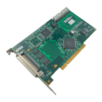
Figure 3-8 shows the RTSI signal connection scheme for PXI TIO devices.
Figure 3-8. RTSI Signal Connection for PXI
+5 V Power Source
The +5 V pin on the I/O connector supplies power from the computer
power supply through a self-resetting fuse. The fuse resets automatically
within a few seconds after removal of an overcurrent condition. The power
pin is referenced to the D GND pins and can supply power to external
digital circuitry. The power rating for this +5 V pin on the NI 660x is
+4.65 to +5.25 VDC at 1 A.
Caution Do not connect the +5 V power pin directly to D GND, RG, or any pin configured
for output on the NI 660x device, or any voltage source or output pin on another device.
Doing so can damage the device and the computer. National Instruments is not liable for
damages resulting from such a connection.
PXI Star 6
CtrnSource
CtrnGate
CtrnAux
CtrnInternalOutput
20 MHz Timebase
Master Timebase
PXI Trigger 7
RTSI Bus Connector
RTSI SwitchRTSI Switch
PXI Trigger
<0..5>
 Loading...