RMX Programmable Power Supplies Safety Information & Installation Guide | © National Instruments | 5
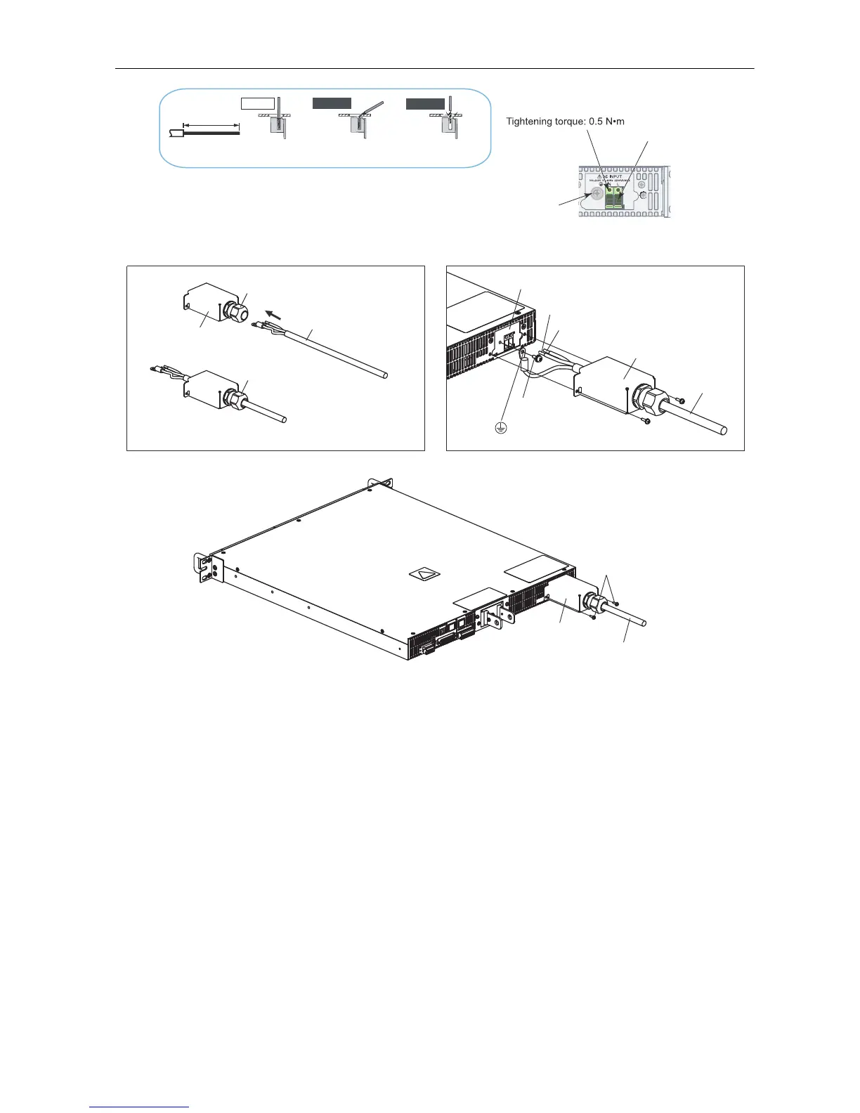
Figure 3. Connecting the Power Cord
5. Attach an appropriate crimping terminal to the switchboard end of the power cord.
6. Turn off the switchboard breaker.
7. Connect the L, N, and (GND) wires of the power cord to the matching terminals on the
switchboard.
STRIP
-
GAUGE
14 mm
Correct
Incorrect
Incorrect
The stripped wire is
touching the chassis.
The wire strands are
touching the chassis.
INPUT terminal cover
INPUT terminal cover
INPUT terminal cover
AC INPUT terminal
L: Black or brown
N: White or blue
(GND)
Screw
: Green or green and yellow
Power cord
Power cord
Power cord
Screw
Use this screw to fix the
wire in place.
Screw M4
Remove the first
14 mm of the wire’s
covering, and then
insert the wire here.
AC INPUT terminal
Cable gland:
Turn left to unlock
Cable gland:
Turn right to lock
Cable gland: Supports wires from 10.5 to 14.4 mm in diameter
 Loading...