RMX Programmable Power Supplies Safety Information & Installation Guide | © National Instruments | 9
Attaching the Output Terminal Cover
You can adjust the diameter of the holes that the load cables pass through by changing the
positions in which the top and bottom halves of the OUTPUT terminal cover are put together.
There are two available positions. Use the appropriate position for the load cables that you are
using.
• For cables that are up to 10 mm in diameter: Put the top and bottom halves of the OUTPUT
terminal cover together so that the hole diameter is small.
• For cables that are between 10 mm and 18 mm in diameter: Put the top and bottom halves
of the OUTPUT terminal cover together so that the hole diameter is large.
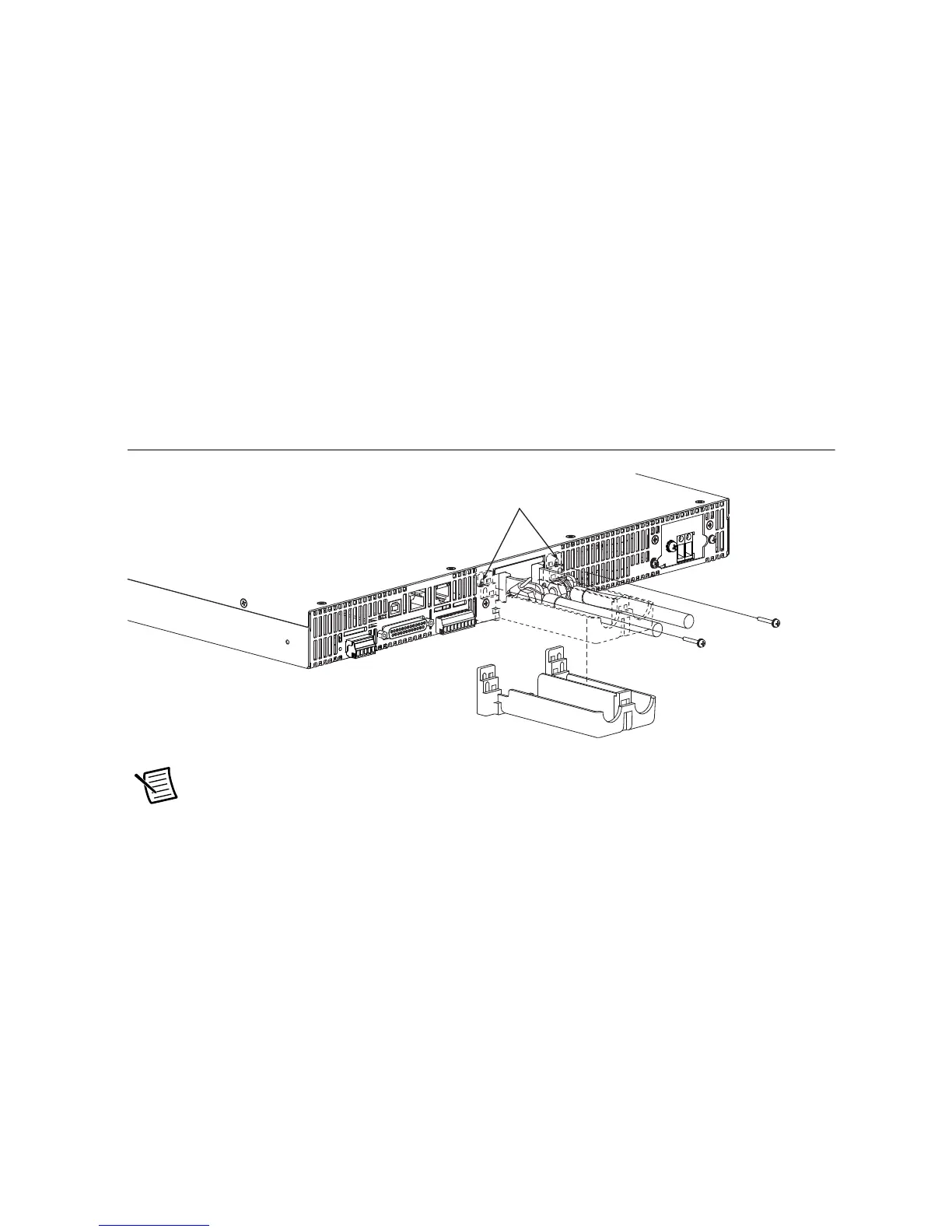
1. Remove the screw that is attached next to the output terminals on the RMX. Use this screw
to attach the OUTPUT terminal cover.
2. Place the bottom half of the OUTPUT terminal cover underneath the load cables connected
to the output terminals.
Figure 9. Attaching Bottom Half of the OUTPUT Terminal Cover
Note The top and bottom halves of the OUTPUT terminal cover have different
shapes.
3. Align the tabs of the top half of the OUTPUT terminal cover with those of the bottom half.
Align the tabs of the OUTPUT terminal cover according to the load cable diameter.
Remove the screws, and then
line up the half of the cover.
 Loading...