8 | NEP-2 Installation Manual
Wiring the NEP-2
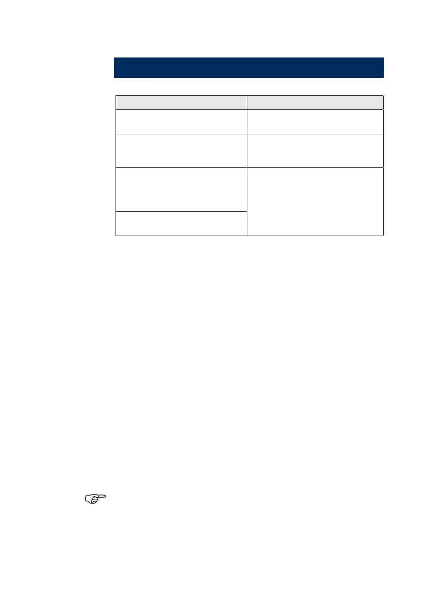
Don’t do this Do this
Don’t make sharp bends in
the cables.
Do make drip and service
loops
Don’t run cables in a way
that allows water to ow
down into the connectors.
Do tie-wrap all cables to keep
them secure
Don’t route the data cables
in areas adjacent to radar,
transmitter, or large current
carrying cables.
Don’t cut or modify the
antenna cable
Power
Before starting the installation, be sure to turn electrical
power off. If power is left on or turned on during the
installation, fire, electrical shock, or other serious injury
may occur. Be sure that the voltage of the power supply
is compatible with the NEP-2 module.
The NEP-2 has a voltage rating of 12 V DC or 24 V DC.
(9 V DC - 32 V DC max range).
The red wire should always be connected to (+) using
a fuse or thermal breaker (5 Amp) to protect the cable.
The NEP-2 is protected by an internal auto resetting
fuse.
The yellow power control wire has to be either:
Common with the red wire (after fuse or breaker) •
Connected in common to the power control wire of a •
display or other device.
If yellow wire is not connected; NEP-2 will be off.
The device applying voltage to the yellow wire must
share a common ground with NEP-2.
The blue wire will not be used, so cap the end of the blue
wire with a wire nut or electrical tape.
 Loading...