19
2.1.2 NPE-A System Diagram
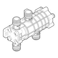
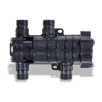
Follow the instructions to install the NaviCirc to the wall.
City water supply
1 2 3 4
ON
SW1
CE1
RA1
U1
CE1
C1
C2
C7
R6
SW1
Q1
12 V SIGNAL
SIGNAL 1
GND
5 V
J1R5
J2
C4
ZD1
R7
D1
CON3CON2
CON1
SIGNAL
SIGNAL 3
GND
SIGNAL 2
Wired
push button
Wired
push button
Wired
push button
HotButton kit*
DHW supply
Return water
Navien NPE A
Water heater
Check Valve
(required)
S
Solenoid
Valve**
Expansion tank***
NaviCirc
Ball
Valve
Ball
Valve
Ball
Valve
Flexible
hoses
Flexible
hoses
Note
A branch from the cold water line must
be connected to the RECIRCULATION
RETURN water connection located on
the water heater. Additionally, the end
user might experience lukewarm water
when rst opening the cold water tap.
Maximum recirculation pipe lengths:
●
100 feet (approx 30 m) equivalent
length of ½” copper pipe
●
400 feet (approx 120 m) equivalent
length of ¾” copper pipe
* The HotButton kit is sold separately.
** Solenoid valve not required under
most conditions. Temperature
uctuations may occur during high
system ow rates.
*** Expansion tank only required if a
check valve is installed on the cold
water supply line or if required by
local codes.
Install the recirculation valve to the faucet furthest from the water
heater.
If installed in close proximity to the water heater, faucets further
away from the water heater will take longer to receive hot water.
 Loading...