53
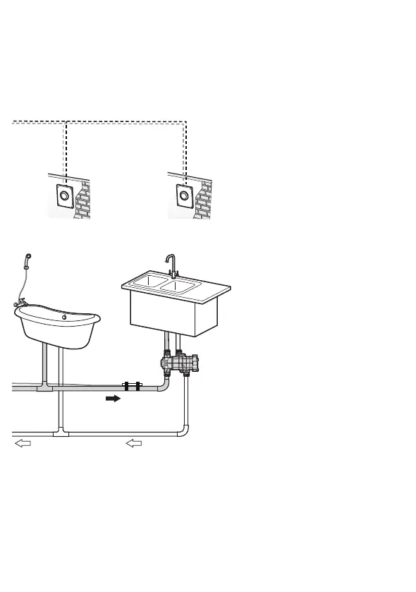
2.3.4 External Recirculation with HotButton (Optional)
and NaviCirc
The following diagram shows the basic operation of an NPN Series
water heater recirculation system with the NaviCirc and HotButton.
1 2 3 4
ON
SW1
CE1
CE2
U1
C1
C2
C7
R6
PC1
12 V 5 V SIGNAL
SIGNAL 1
GND
R5
R9
R8
C3
R1
R2
R7
D1
CON3
CON5
CON2
CON1
SIGNAL 2
SENSOR I
RA1
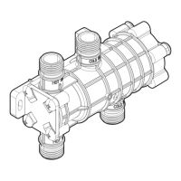
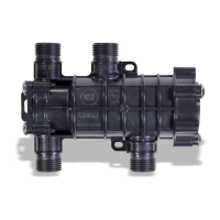
Check Valve
Expansion Tank
City Water Supply
DHW Supply
Push button
contact signal
Ball
Valve
External Pump
HotButton
Kit*
Check
Valve
External
Pump
Connector*
1 2 3 4
ON
SW1
CE1
CE2
U1
C1
C2
C7
R6
PC1
12 V 5 V SIGNAL
SIGNAL 1
GND
R5
R9
R8
C3
R1
R2
R7
D1
CON3
CON5
CON2
CON1
SIGNAL 2
SENSOR I
RA1
Return Water
Temperature Sensor**
NaviCirc
Push button
contact signal
Push button
contact signal
* The Hotbutton kit and
external pump connector
are not included with the
water heater but they are
available for purchase. For
more information about
connecting the external
pump to the water heater,
refer to “2.5.1 External
Pump Wire Connection”
on page 42.
** When the optional
temperature sensor
is installed, it must be
insulated. The sensor wire
may be extended by up to
100 ft (30 m) using 22AWG
wire.
 Loading...