UPSIDE-DOWN MICRO-EMITTERS HANDBOOK
21
MICRO-SPRINKLERS/EMITTERS ASSORTMENT
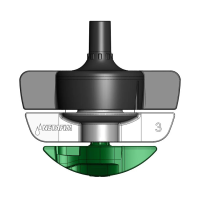
Water trajectory
T
D
Swivel (rotor)
T. Trajectory
height (cm)
D. Distance
from head (cm)
LR 50 175
FLT 40 175
SR 15 165
Trajectory height at distance from emitter head
Pressure: 2.5 bar, at any flow rate (50-200 l/h)
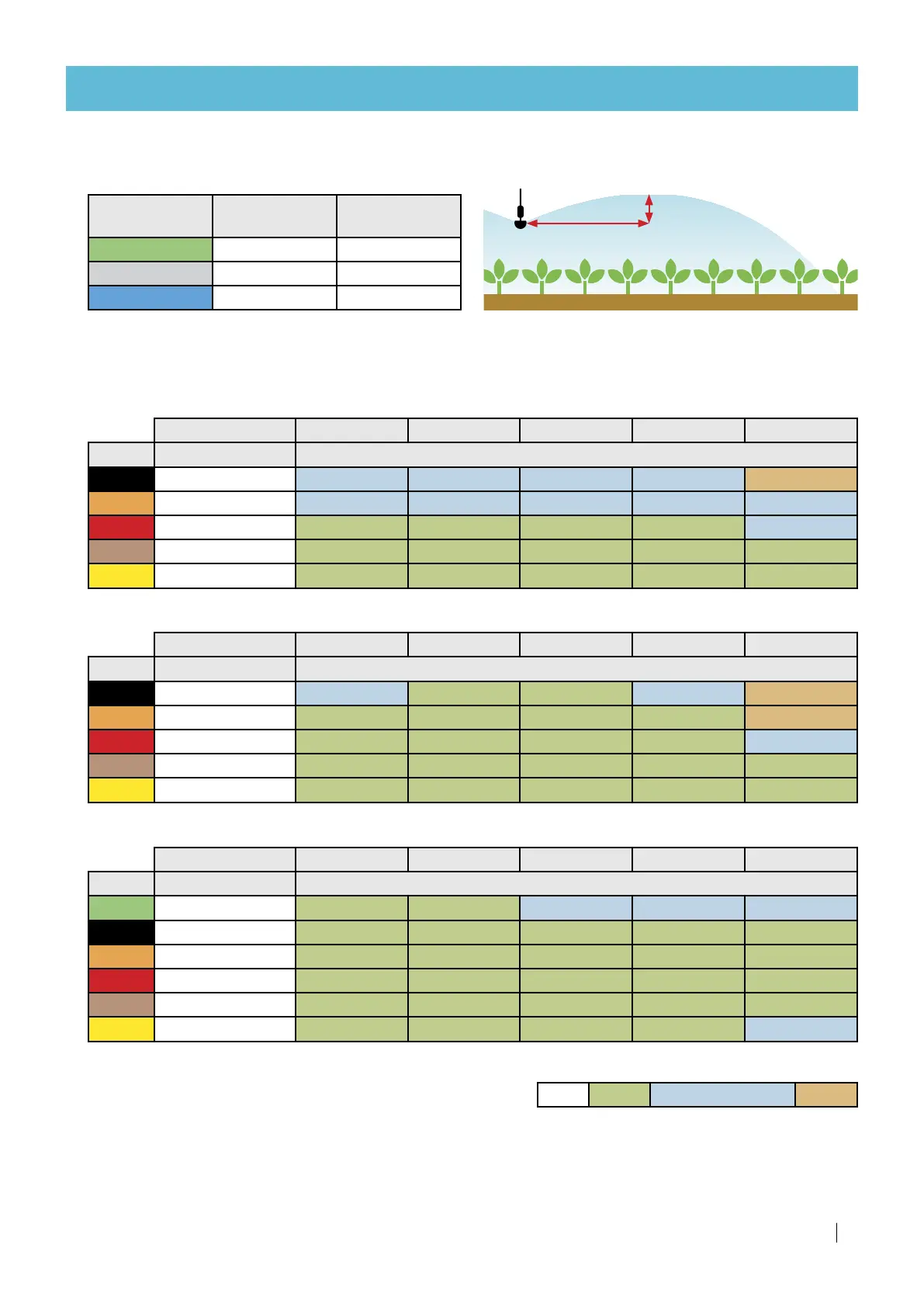
Distribution uniformity at different spacings - rectangular pattern
LR (Green rotor)
Spacing (m x m) › 1.0 x 5.0 1.5 x 5.0 2.0 x 5.0 2.5 x 5.0 3.0 x 5.0
Nozzle Real flow rate* Precipitation rate (mm/h)
070 70.0 14.0 9.3 7.0 5.6 4.7
090 94.5 18.9 12.6 9.5 7.6 6.3
120 125.0 25.0 16.7 12.5 10.0 8.3
160 183.0 36.6 24.4 18.3 14.6 12.2
200 207.0 41.4 27.6 20.7 16.6 13.8
FLT (Gray rotor)
Spacing (m x m) › 1.5 x 3.2 2.0 x 2.0 2.0 x 3.0 2.0 x 3.2 2.0 x 4.0
Nozzle Real flow rate* Precipitation rate (mm/h)
070 70.0 14.6 17.5 11.7 10.9 8.8
090 94.5 19.7 23.6 15.8 14.8 11.8
120 125.0 26.0 31.3 20.8 19.5 15.6
160 183.0 38 .1 45.8 30.5 28.6 22.9
200 207.0 4 3.1 51.8 34.5 32.3 25.9
SR (Blue rotor)
Spacing (m x m) › 1.0 x 2.0 1.5 x 2.0 1.5 x 2.5 2.0 x 2.0 2.0 x 2.5
Nozzle Real flow rate* Precipitation rate (mm/h)
050 52.2 26.1 17.4 14.5 13.1 10.4
070 70.0 35.0 23.3 19.4 17. 5 14.0
090 94.5 47.3 31.5 26.3 23.6 18.9
120 125.0 62.5 41.7 34.7 31.3 25.0
160 183.0 91.5 61.0 50.8 45.8 36.6
200 207.0 103.5 69.0 57.5 51.8 41.4
*Distribution uniformity tests under laboratory conditions,
micro-sprinkler/emitter head at 1.8 meter above surface,
at 2.5 bar working pressure at the emitter head.
The layouts, distances, working pressures and heights-above-surface presented in the tables above are
solely for demonstration purposes. There are countless additional configurations for micro-emitter placement.
To acquire accurate distribution data for a specific crop, contact the pertinent Netafim™ technical team.
%CU
≥ 94% ≥ 89% and < 94% < 89%
Legend
 Loading...