© 2005 Alamo Group Inc.
Section 5 - 11
Maverick (NH TS-100A,115A ,125A/,35A Asy. Man) 01/05
Frame Installation
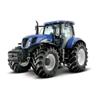
Boom Rest
Weldment
P/N 02982314
(f/24 ft. boom)
&
P/N 02982025
(f/ 30 ft. boom)
Figure 29
Figure 31
Figure 30
7. Install LH Axle Strap. The Axle Strap bolts
down over the top of the Axle (LH Side) and bolts run
through the Rear Frame rails. The RH Side the axle
strap is part of the boom support brace weldment
and also bolts down over the axle with the bolts
through the rear frame rail (See Figure 30 & 31)
Make certain that all the bolts mounting the
frame components and the boom rest are properly
torqued, see the bolt torque chart.
8. Reinstall LH Rear Tire and Wheel. Reinstall
the LH rear Tire and Wheel now if it has not already
been done. Use a hoist to lift and secure the rear
tires is recommended as they are very heavy.
Figure 28
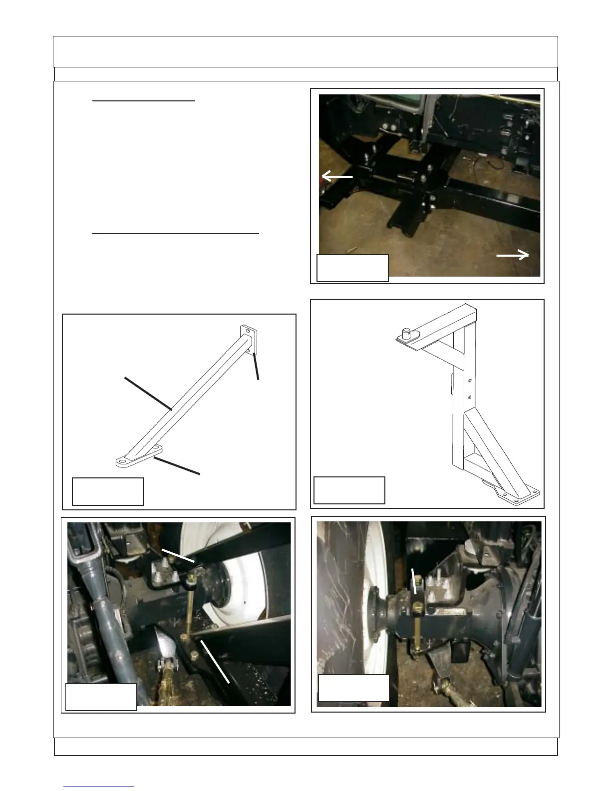
Boom Rest
Support Weldment
P/N 02982022
(f/24 ft or 30 ft.. boom)
Bolts to
boom rest
Bolts to top of
tractor axle
LH side of tractor Upper
axle strap
P/N 02980694
Boom Rest
Boom Rest Support
& Axle Strap
Weldment
Figure 27
Shown from LH
side of tractor
Rear
Front
 Loading...