English – 2
PRODUCT DESCRIPTION AND
INTENDED USE
1
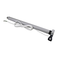
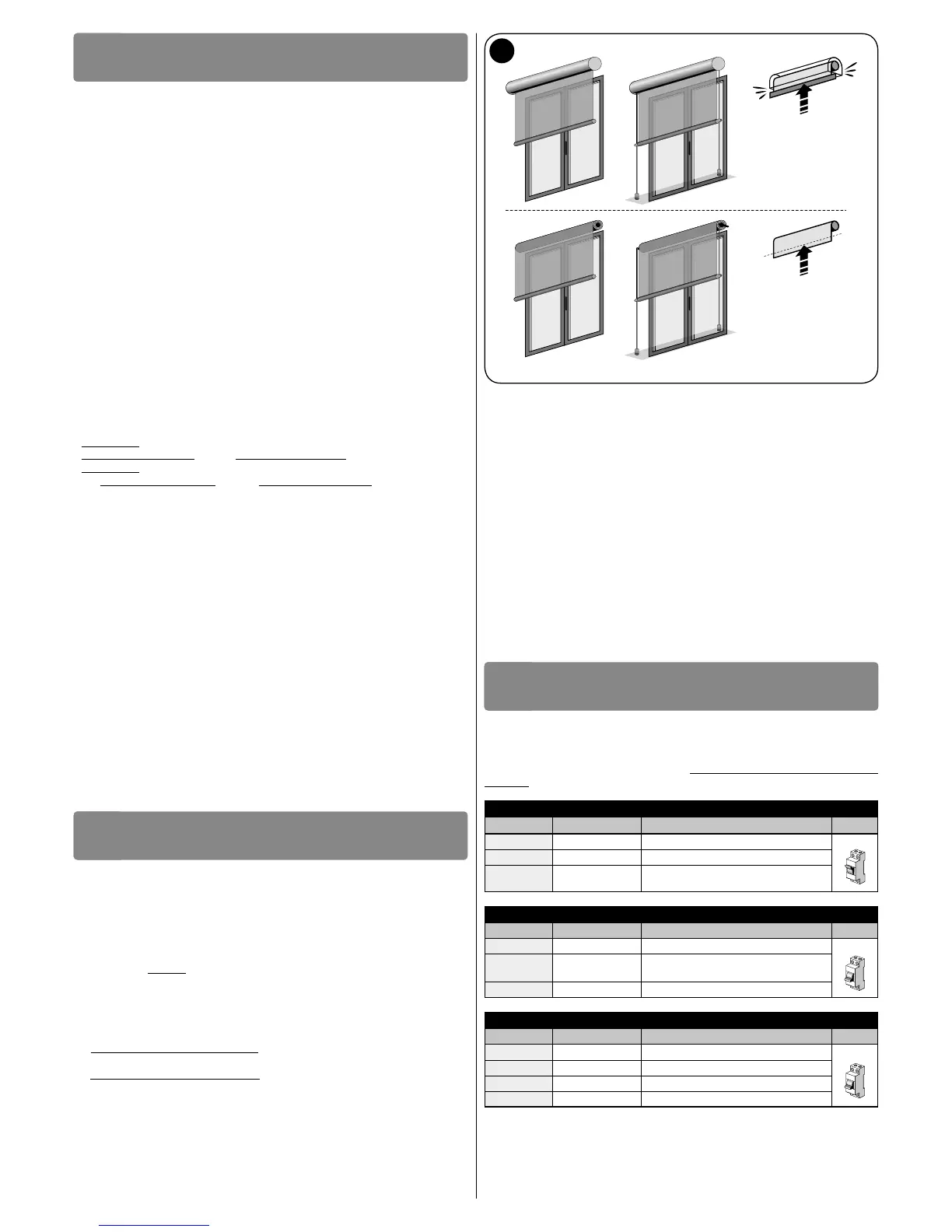
This product is a tubular motor for automating indoors roll-up awnings, or indoors
sunscreens, or similar roll-up equipment (fig. 2). Do not use it for any other pur-
pose! The manufacturer declines all liability for damage resulting from im-
proper use of the product or any other use than that specified in this manual.
The product has the following functional characteristics:
• it is mains powered (see the motor’s nameplate ratings);
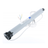
• it is equipped with three separate connection cables: one power cable, one com-
mand cable and one smart-bus data cable;
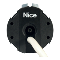
• it installs inside the winding roller; the part of the motor that protrudes from the roller
(electronic head) mounts to the ceiling or wall with brackets (not included);
• it has a built-in control unit with encoder technology that electronically controls the
movement and precision of the limit switches;
• it can be programmed using the DMBM module, BUS T4 and a dedicated program-
mer (TTP, etc.), or from a smartphone with “NFC” technology. These accessories
are not included; In particular programming with the DMBM module permits a high
level of customisation. For example, programming “awning movement speed” us-
ing a TTP programmer, you can only choose one of five values, while programming
the same parameter with the DMBM module allows you to set any value between
“vmin” and “vmax”;
• it can be commanded from a cabled wall-mounted push button panel or from the
DMBM module (fig. 3). These accessories are not included;
• it can move the awning up or down; stop it at the upper limit switch, the lower lim-
it switch or various intermediate positions. Controlling the motor with the DMBM
module allows you to use advanced commands such as moving to a particular po-
sition at a particular speed.
EXAMPLE 1: 30% @ 21 rpm – the awning moves to 30% of its travel between the
down limit switch at 0% and the up limit switch at 100%, at a speed of 21 rpm.
EXAMPLE 2: 100% @ 32 rpm – the awning moves to 100% of its travel between
the down limit switch at 0% and the up limit switch at 100% (therefore to the up
limit switch) at a speed of 32 rpm.
• awnings of different weights are moved at the same speed;
• the up and down speeds are the same provided the settings are equal;
• it allows you to adjust the movement’s duration;
• it allows you to set acceleration and deceleration at the start/end of the movement
respectively;
• it features a security system that detects the presence of an obstacle along the
awning travel, immediately blocking the movement in progress and performing a
brief inversion of movement. The same system is automatically activated at the end
of the Up movement (only if the upper limit switch “0” consists of a box or other me-
chanical stop), to mitigate the impact of the awning against the housing and loosen
the tension exerted by the motor on the canvas, when the awning is stationary at
the upper limit switch “0”.
• it enables you to set the functional logic of a button panel’s buttons;
• it enables you to precisely adjust the limit switches with the buttons on the mo-
tor head;
• it has an integral led that indicates system status and any malfunctions;
• it is equipped with a thermal protection system which, in the case of overheating
caused by overuse of the automated mechanism (beyond the indicated limits, see
the Technical Specifications chapter), automatically cuts off the electricity supply,
restoring it as soon as the temperature returns to normal;
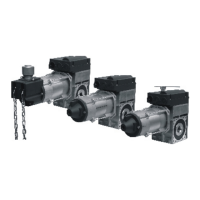
• it is available in a variety of versions, each with a specific motor torque (see the mo-
tor nameplate ratings).
INSTALLATION OF THE MOTOR AND
THE ACCESSORIES
2
2.1 - Preliminary checks before installation and lim-
itations on use
• Check the condition of the product right after unpacking it.
• Make sure that the torque, the rotation speed and time of operation of this motor
are suitable for automating your awning. In particular, do not install the motor if
its torque is greater than that needed to move your awning. To choose the
right motor to the technical features of your awning refer to the the “Guide to Se-
lection” section, in the “Nice Screen” catalogue, – also available on www.nicefory-
ou.com.
• Check the diameter of the winding roller. This must be chosen according to the
motor torque, as follows:
– For motors of size “S” (Ø = 35 mm) the minimum inside diameter of the winding
roller must be 40 mm;
– For motors of size “M” (Ø = 45 mm) the minimum inside diameter of the winding
roller must be 52 mm;
• Additional limitations on use are listed in chapters 1 and 2 and in the technical
characteristics on the nameplate.
2.2 - Assembling and installing the tubular motor
Caution! – Read the safety warnings before proceeding. Incorrect installa-
tion could cause severe physical injury.
To assemble and install the motor, refer to fig. 4 (the accessories shown in fig. 4 are
not included in the package). To select the limit switch gear wheel (fig. 4-a), drive
wheel (fig. 4-b), motor bracket (fig. 4-f), or to select supplementary cables (of dif-
ferent lengths), refer to the “Nice Screen” catalogue, which is also available on www.
niceforyou.com.
2.3 - Installation of accessories
After installing the motor, install the accessories, if required. In order to identify those
that are compatible and choose the models desired, see the “Nice Screen” cata-
logue, which is also available on www.niceforyou.com. Fig. 3 shows the type of ac-
cessories that are compatible and their connection to the motor (all of these are op-
tions and not included in the package)
ELECTRICAL CONNECTIONS AND
FIRST POWER UP
3
The motor is equipped with three separate cables: one power cable, one com-
mand cable and one Nice smart-bus data cable. Each cable has a connector for
connection to the motor (fig. 4-h); the connectors are removable and allow the re-
placement of cables (fig. 4-i). CAUTION! - The smaller cables must be handled
carefully because they contain very thin wires that could be damaged.
CABLE “A” is the POWER cable (fig. 3)
Wire Colour Connection
A1 Brown Power supply phase
 Loading...