1 - GENERAL WARNINGS: SAFETY - INSTALLATION - USE
(Instructions translated from Italian)
CAUTION Important safety instructions. Follow all instructions as improper instal-
lation may cause serious damage
CAUTION Important safety instructions. It is important for you to comply with these
instructions for your own and other people's safety. Keep these instruc-
tions
• Before commencing the installation, check the “Product technical specications”, in particular
whether this product is suitable for automating your guided part. If it is not suitable, DO NOT
continue with the installation
• Before proceeding with the installation of the product, check that all materials are in good work-
ing order and suited to the intended applications
• The product is not intended for use by persons (including children) with reduced physical, sen-
sory or mental capacities, nor by anyone with insufcient experience or familiarity
• Children must not play with the appliance
• Do not allow children to play with the control devices of the product
CAUTION In order to avoid any danger from inadvertent resetting of the thermal cut-off de-
vice, this appliance must not be powered through an external switching device,
such as a timer, or connected to a supply that is regularly powered or switched
off by the circuit
• Provide a disconnection device (not supplied) in the plant’s mains power supply, with a contact
opening distance that permits complete disconnection under the conditions dictated by over-
voltage category III
• Handle the product with care during installation, taking care to avoid crushing, denting or drop-
ping it, or allowing contact with liquids of any kind. Keep the product away from sources of heat
and naked ames. Failure to observe the above can damage the product, and increase the
risk of danger or malfunction. If this should happen, stop installation immediately and contact
Customer Service
• The manufacturer assumes no liability for damage to property, items or persons resulting from
non-compliance with the assembly instructions. In such cases the warranty for material defects
is excluded
• Before working on the system (maintenance, cleaning), always disconnect the product from the
mains power supply
• The packing materials of the product must be disposed of in compliance with local regulations
• If the product is damaged do not try to x it and please contact the Service Centre
2 - PRODUCT DESCRIPTION AND INTENDED USE
• Barrier controls
• Gate and door controls
• Parking and trafc managing
- Warning! All uses other than the described use and use in environmental conditions
other than those indicated in this manual should be considered improper and forbidden!
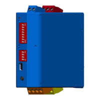
3 - FUNCTIONAL SPECIFICATIONS
The LP21 inductive loop detector is a system used for detecting vehi-
cles by means of inductive loops with the following characteristics:
• Galvanic isolation between loop and electronic parts of the detector
• Automatic adjustment of the system after power up
• Continuous balancing of frequency drift
• Suitable for monitoring individual parking spaces
• Sensitivity can be set regardless of the loop inductivity
• Occupied loop message reported by the LED indicator
• Relay 0V contacts for continuous signal and pulse signal
• Output pulse signal from the loop
• Indication of the loop frequency via LED
• Loop connection available for Diagnostics
In the design and installation of inductive loops,
you should take into consideration the table
opposite.
A normal insulated copper wire, preferably with a
cross-section of 1.5 mm
2
, can be used to create
the loop.
Lay the cable,with the number of windings indi-
cated in the table. The two cable ends must be
intertwined (at least 20 times per meter) from the
loop to the detector.
Table
Loop perimeter number of windings
less than 3 m.
6
from 3 to 4 m. 5
from 4 to 6 m. 4
from 6 to 12 m. 3
over 12 m.
2
4 - PROGRAMMING
4.1 - Sensitivity
The sensitivity setting determines the change in frequency that a vehicle must cause in order to
use the output of the detector. The sensitivity setting can be adjusted on 4 levels by means of the
two DIP Switch ‘s’ located in the front part of the loop detector (see table 1).
Table 1
Sensitivity level “s” DIP Switch
1 low (0.64 % Δf/f)
2 (0.16 % Δf/f)
3 (0.04 % Δf/f)
4 high (0.01 %
Δ
f/f)
4.2 - Delay and reset
The delay can be set with the ‘h’ DIP Switch.
After the delay time has elapsed, a message indicating “loop unoccupied” is displayed and a new
recalibration of the loop is started automatically. The delay starts when the loop is occupied (see
table 2).
Table 2
Delay “h” DIP Switch
5 minutes
Uninterrupted
When switching on the power supply voltage, the detector will adjust the loop frequency. If there
are brief outages in voltage (< 0.1 s), no new adjustment will take place.
A reset with a new adjustment can be activated manually by changing the delay time.
4.3 - Operating principle of the presence relays
The presence signal and the pulse signal of the detector are both provided with a 0V contact relay.
The operating principle of the relay for the presence signal can be selected with the ‘r’ DIP Switch
(see table 3).
Table 3
Delay “r” DIP Switch
When the signal is sent, the relay coil is energised and the con-
tact opens
When the signal is sent, the relay coil is de-energised and the
contact closes
4.4 - Frequency setting
The operating frequency of the detector can be set at 2 levels on the 3-pole front terminal block.
The permitted frequency range is between 30 kHz and 130 kHz. The frequency depends on the
chosen frequency level, and the inductivity resulting from the geometry of the loop, the number of
windings on the loop and the loop's power supply line.
up = high frequency down = low frequency
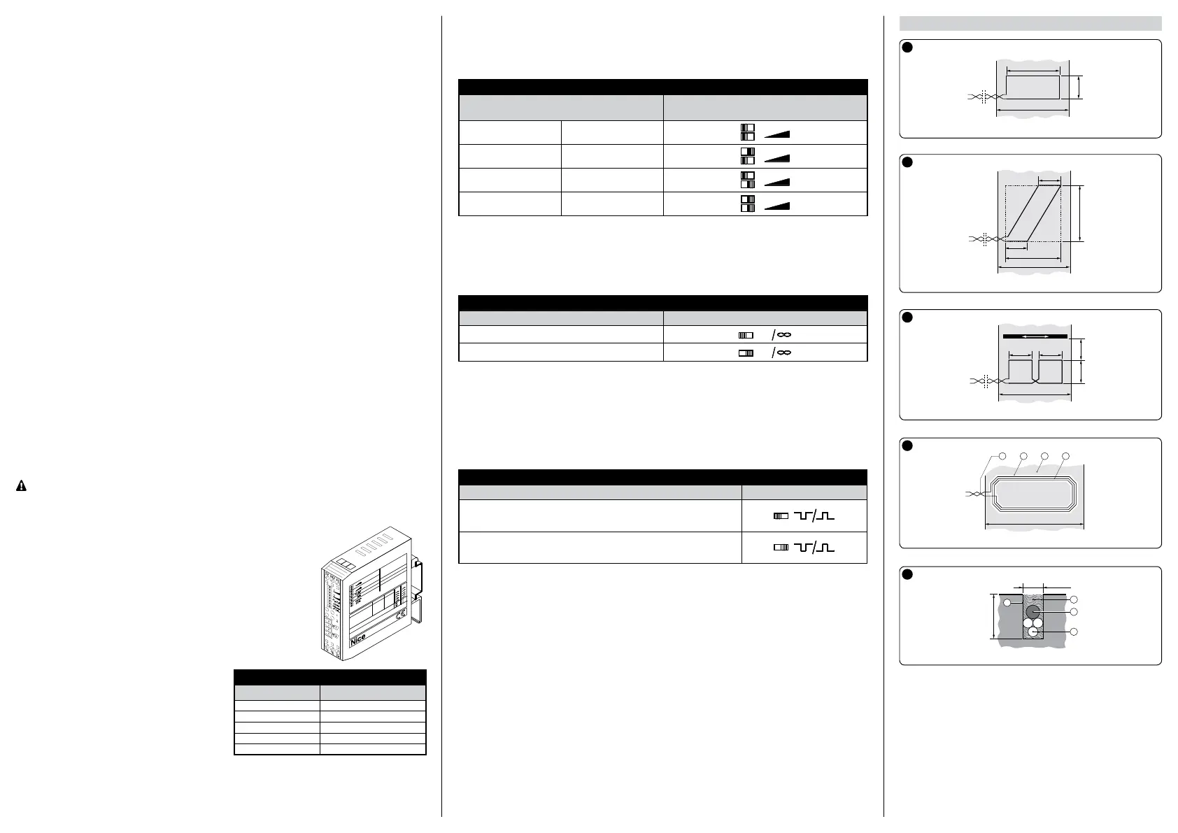
Installation examples
1
2
3
4
5
Fig. 1 - Recommended for cars, lorries, buses
Fig. 2 - Recommended for motorbikes and bicycles
Fig. 3 - Applications requiring low sensitivity at the side
Fig. 4 - (A) Floor (B) Twisted wire (C) Groove (D) Loops
Fig. 5 - (A) Sealant (B) Groove (C) Twine (D) Loops
 Loading...