3
4. Connect the BLACK to the terminal labeled
COMMON, and the BLUE wire to terminal in
STEP 3 to open gate. See wiring diagrams to the
right for guidance on wiring the sensor to your
gate opener’s control board.
5. Connect the POWER INPUT wires from the
Exit Wand Sensor (if not already connected to a
terminal on the board).
• Connect the YELLOW and BRAIDED
GROUND wires to the
(–)
NEGATIVE side of
power source (i.e. battery).
• Connect the RED wire to the
(+)
POSITIVE
side of power source (i.e. battery).
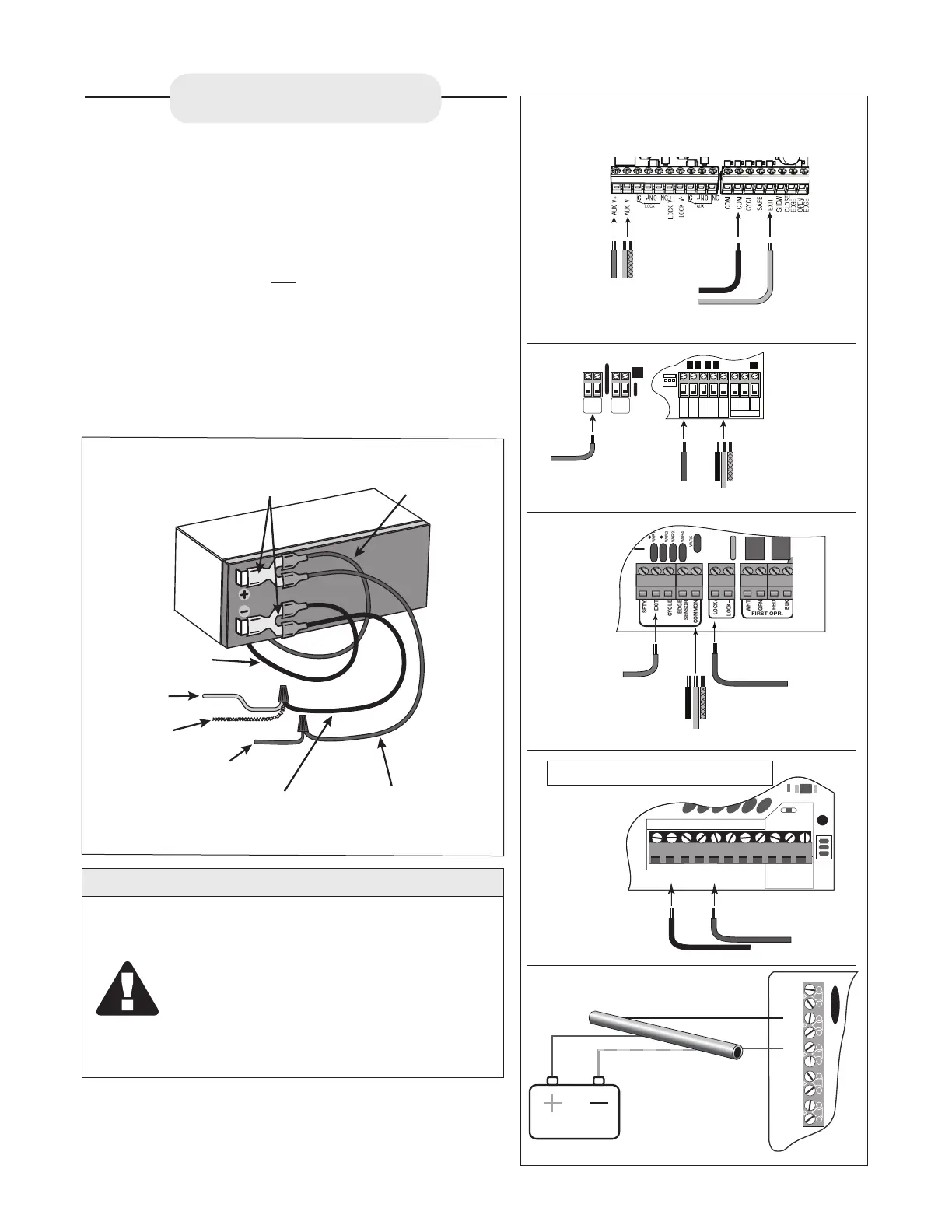
TURN GATE OPENER OFF
Connect the BLACK
wire from the SENSOR
CABLE to one of the
COMMON terminals on
the opener control board.
Connect the RED
wire from the SENSOR
CABLE to the AUX V+
terminal on the opener
control board.
Connect the YELLOW
wire and BRAIDED GROUND
wire from the SENSOR
CABLE to the AUX V- terminal
on the opener control board.
Connect the BLUE
wire from the SENSOR
CABLE to the EXIT
terminal on the opener
control board.
BLUE
RED
YELLOW + BRAIDED
BLACK
RECR
GRN
BLK
RED
EXIT
SAFETY
EDGE
CYCLE
COMMON
LINK
Connect the
BLUE wire from
the SENSOR
CABLE to the
EXIT terminal on
the opener
control board.
Connect the RED
wire from the
SENSOR CABLE
to the H AUX OUT
terminal on the
opener board.
Connect the BLACK
wire, YELLOW wire and
BRAIDED GROUND
wire from the SENSOR
CABLE to one of the
COMMON terminals on
the opener control board.
BLUE
BRAIDED
YELLOW
BLACK
AUX
OUT
SOLAR
INPUT
18VAC/
H L
RECEIVER
ALM
RCVR.
COM
GRN
BLK
RED
CYCLE
SAFETY
EXIT
SHADOW
OPEN
EDGE
COM
CONTROL INPUTS
CLOSE
EDGE
Connect the BLUE wire from
the SENSOR CABLE to the
EXIT terminal on the opener
control board.
Connect the BLACK wire
from the SENSOR CABLE
to one of the COMMON
terminals on the opener
control board.
BLUE
See the diagram to the left for battery connection instructions
for the RED, YELLOW AND BRAIDED GROUND wires.
WIRING DIAGRAM EXAMPLES
NOTE: Power Input Connections Not Shown.
(See gate instruction manual for complete instructions)
BRAIDED GROUND
from SENSOR Cable
YELLOW wire from
SENSOR CABLE
RED wire from SENSOR Cable
Battery Cable
BLACK (-)
BLACK BATTERY CONNECTION WIRE
with Spade Connector included with SENSOR
RED BATTERY CONNECTION WIRE
with Spade Connector included
with SENSOR
Double Spade Connectors
included with SENSOR
Battery Cable
RED (+)
VAR5
K1
PF1
K2
BATT +
K3
K4
VAR4
VAR3
VAR2
VAR1
SFTY.
EXIT
CYCLE
EDGE
SENSOR
COMMON
LOCK+
LOCK–
WHT
GRN
RED
BLK
WHT
GRN
SECOND OPR.FIRST OPR.
RED
BLK
14 VAC
OR
SOLAR
Connect the BLUE wire from
the SENSOR CABLE to the
EXIT terminal on the opener
control board.
Connect the RED wire from
the SENSOR CABLE to the
LOCK+ terminal on the
opener control board.
Connect the
BLACK wire,
YELLOW wire and BRAIDED
GROUND wire
from the
SENSOR CABLE to one of the
COMMON terminals on the
opener control board.
BLUE
RED
BRAIDED
YELLOW
BLACK
POWER
CHGR
CHGR
EDGE
CYCLE
EXIT
SAFETY
COM
COM
LOCK+
LOCK -
Battery
Vehicle
Sensor
IMPORTANT
WHEN THE WAND IS FIRST POWERED UP IT
MUST BE UNDISTURBED FOR 60 SECONDS
TO PERFORM THE SELF TEST AND
CALIBRATIONS. BEFORE POWERING THE
WAND MAKE SURE THERE ARE NO MOVING
METAL OBJECTS OR MOVING VEHICLES
WITHIN THE RANGE OF
THE WAND
6. Turn opener ON and TEST.

 Loading...