EasyManua.ls Logo

Nice Moby 5000 Series User Manual

Default Icon
79 pages
To Next Page IconTo Next Page
To Previous Page IconTo Previous Page
Page #30 background image
50
45
40
35
30
25
20
15
10
25
22
20
17
15
12
10
7
5
17
15
13
12
10
8
7
5
3
13
11
10
8
7
6
5
4
3
10
9
8
7
6
5
4
3
2
100
1m
kg
2345
120 140 160 180 200 220 240 260 280
AB
lunghezza cancello
mm
28
MB4005 - MB4015 - MB4024 - MB4605 - MB4615
butée de fin de course en ouverture
MB4006
butée de fin de course en ouverture et en fermeture
MB5015 - MB5024 - MB5615
butée de fin de course en ouverture
MB5016
butée de fin de course en ouverture et en fermeture
ligne d’installation conseillée
Valeurs en ouverture Valeurs en fermeture
4 Le graphique ci-dessous est utile pour déterminer la force
maximum à l’extrémité du portail en fonction des valeurs de A et B
longueur portail

Table of Contents

Question and Answer IconNeed help?

Do you have a question about the Nice Moby 5000 Series and is the answer not in the manual?

Nice Moby 5000 Series Specifications

General IconGeneral
Operating temperature-20°C to +50°C
Max. gate leaf length5 m
Max. gate leaf weight500 kg
Maximum Gate Weight500 kg
Maximum Gate Width5 m
Power supply230V AC
Motor TypeElectromechanical

Summary

Instructions and Warnings for the Fitter

Important Information

Installation

Preliminary Checks

Checks before installation for gate suitability, balance, smoothness, and packaging.

Limits of Use

Defines gate weight and length limits, considering shape, height, and weather conditions.

Assembly

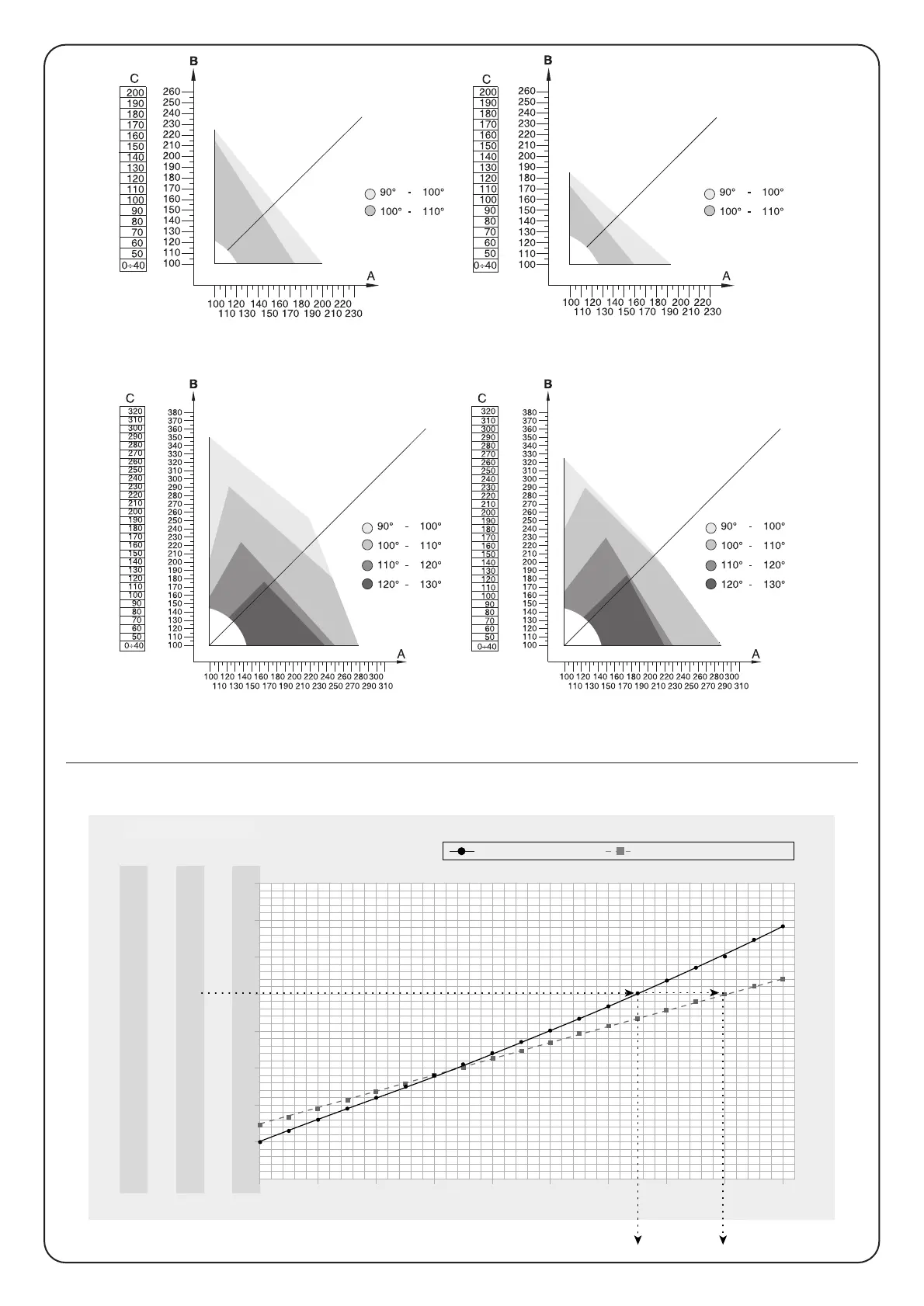
Guidance on assembling the system, including projection, angle, speed, and thrust.

Fixing the Rear Bracket

Steps to measure C, find B on graphs, and determine bracket fixing points.

Fixing the Front Bracket

Instructions for attaching the front bracket to the gate according to specific distances.

Opening the Gate Outwards

Guidance on using a longer bracket if necessary for correct gate movement.

Adjusting the Limit Switch

How to adjust limit switches for precise gate stop positions and safety.

Mounting the Electric Lock (Optional Accessory)

Steps for mounting an optional electric lock for enhanced security.

Typical System Layout

Diagram illustrating the typical arrangement of components in a gate automation system.

Electrical Connections

Details on connecting the gear motor wires to the control unit connector.

Manual Manoeuvre or Release

Testing

Maintenance

Disposal

Guides on proper disposal of materials according to country laws and waste sorting.

Technical Specifications

Models and Characteristics

Overview of different MOBY models and their key features like voltage and stop type.

Instructions and Warnings for Users of the MOBY Gear Motor

Related product manuals