GB
13
Switch 9: On = Brake
At the end of the movement a motor brake procedure is performed, initially slight and then more incisive in order to stop the gate rapidly but
without jolts.
This function controls photocell efficiency at the beginning of each manoeuvre. See the “Phototest” chapter.
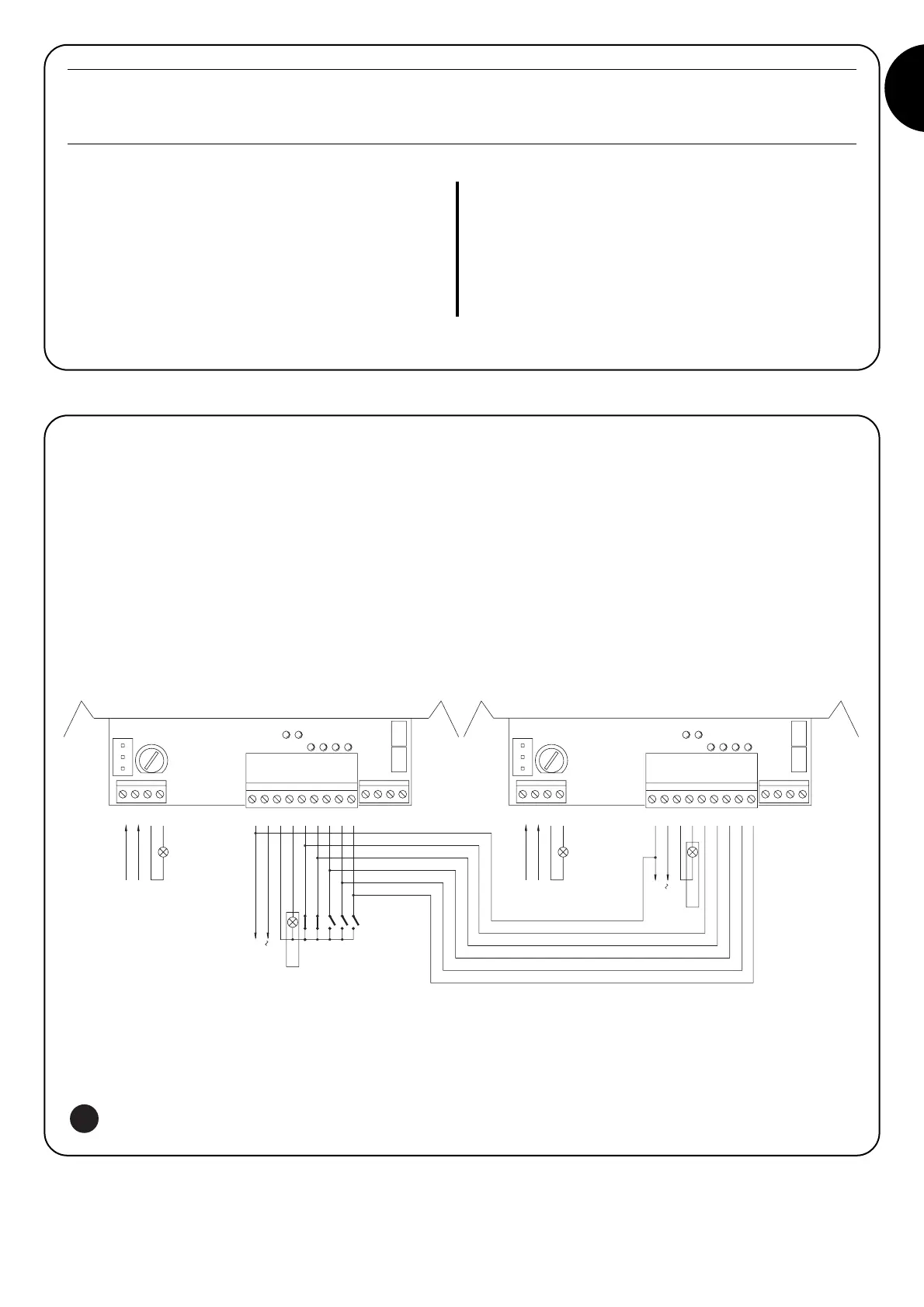
To create an automation system working with 2 opposed leafs:
• Use two motors with the control units connected as indicated in
fig. 5.
• Connect the flashing light and the “Gate Open Indicator” to any
one of the two control units .
• The inputs must be connected in parallel.
• The “Common” of the inputs can be connected to one of the 2
control units.
• Connect the 0Volts (Terminal 5) of the two control units.
• The “Phototest” function must not be used
• The “Condominium” function ( Dip-Switch 3) should be fitted as
this allows the leafs to be resynchronised if the 2 control units
become unsynchronised.
7) Using 2 control units on opposed leafs
Switch 10: On
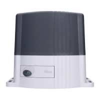
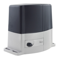
ROBO - THOR
Without the PIU board fitted:
• Gate open indicator with proportional flashing
With the PIU board fitted:
• “Phototest”
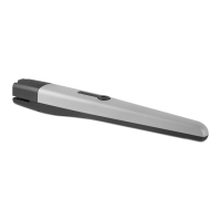
OTTO
Without the PIU board fitted:
• Courtesy light time = 4 minutes
With the PIU board fitted:
• “Phototest”
 Loading...