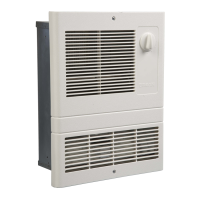
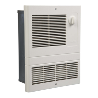
MODEL • 112
®
Page 2
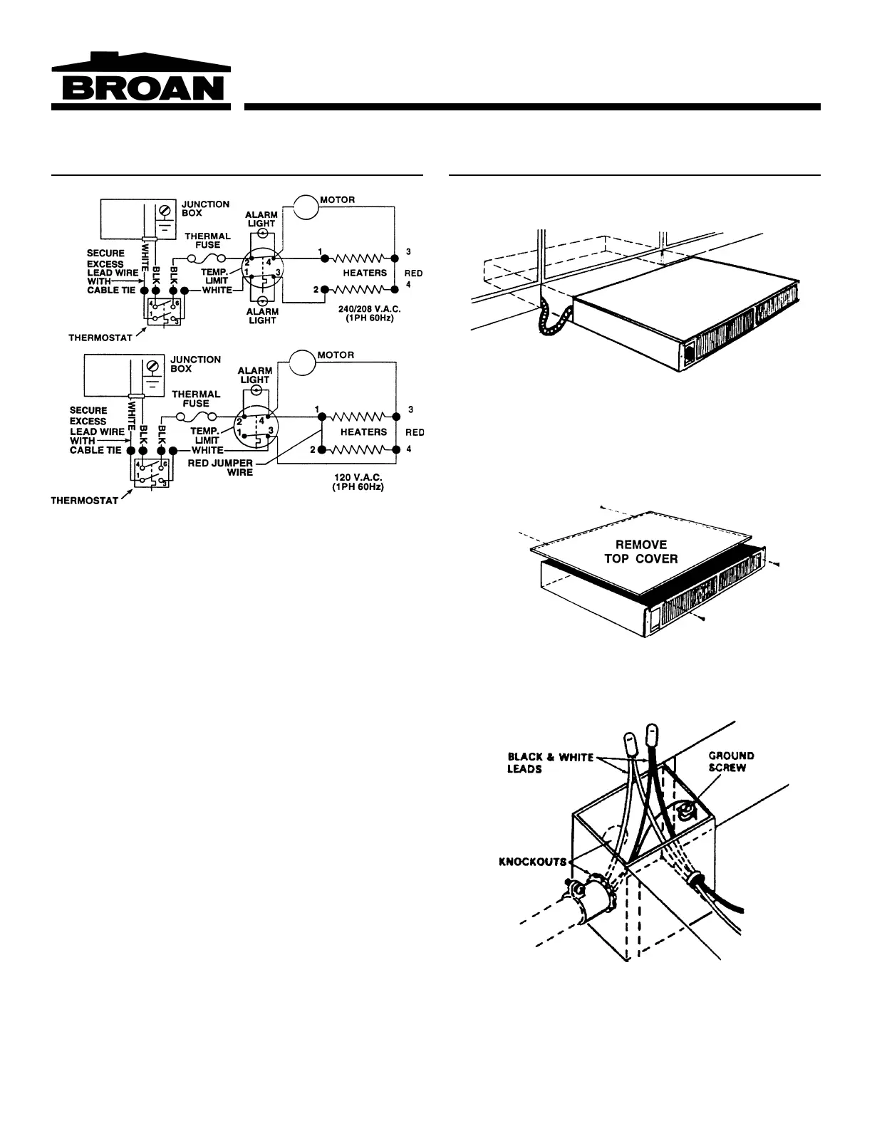
FIELD CONVERSION TO 120 V.A.C.
If a 120 V.A.C. circuit is to be used, make wiring changes as fol-
lows:
1. Disconnect white wire from heater element terminal “2” and
connect it to terminal “4.” The heater will now operate at 120
V.A.C., 750W, 6.3A.
2. For 120 V.A.C, 1500W, 12.5A operation, add the short red
jumper wire (provided) between terminals “1” and “2”.
3. Remove alarm light wire leads from terminals “1” and “3” of the
high temperature limit. Remove white wire lead from limit ter-
minal “1” and reconnect at limit terminal “3”. Secure wire leads
with wire tie so there is no interference with unit operation.
NOTE: Terminal numbers are marked on the side of the blower
housing, above the heater elements.
WIRE THE UNIT
WARNING: Disconnect power at service entrance before wir-
ing this product.
1. Run electrical power cable to installation location. Provide two
feet of slack to allow heater to be pulled out far enough to re-
move top cover for cleaning or servicing.
NOTE: It is recommended that flexible conduit be used for field
wiring to the unit to protect the wires from sharp objects or hazard-
ous environments.
NOTE: Be sure supply voltage meets the equipment requirement.
Refer to the rating plate, unit wiring diagram and specification table.
2. Remove top cover for access to wiring box at rear of heater.
3. Remove one of the two knockouts and connect power cable to
heater using appropriate connector. Allow at least six inches of
wiring inside of wiring box.
4. Connect black to black, white to white and green (or bare wire)
to ground screw, as shown. Tuck wires down inside the wiring
box.
5. Replace top cover.
WARNING: Do not operate heater without top cover in place.
6. Slide heater into place and secure to mounting surface.