15
BX61WI
Fig. 5
Fig. 6
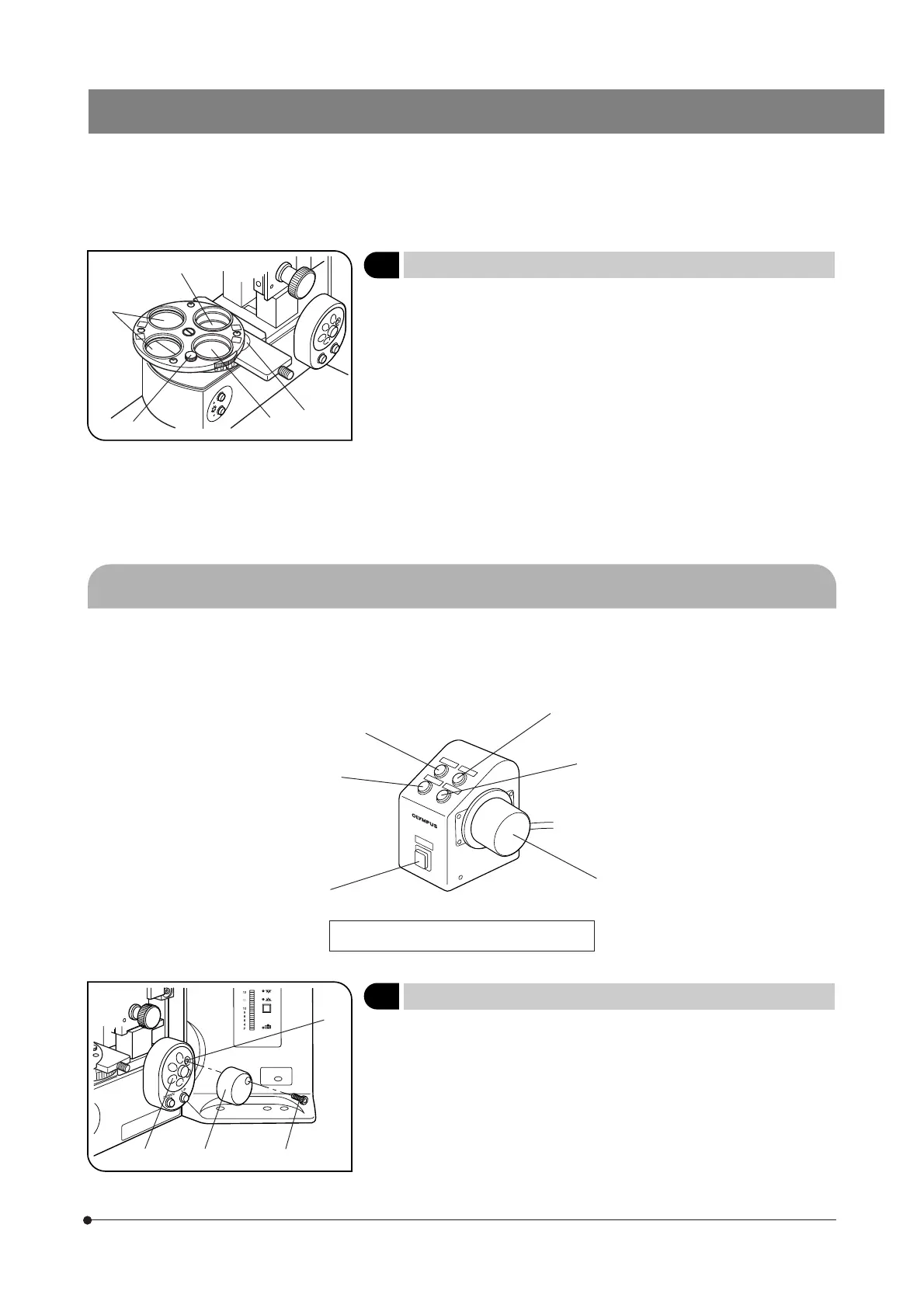
4 Using the Filter Turret
(Fig. 5)
}Filters with a diameter of 32 mm can be inserted in positions 1 to 4.
1. Filter positions 1 2 are rotatable. When the 32PO or 32POIR polarizer is
placed in either position, the polarizer can be fixed by a push ring.
}When filter position 1 is engaged in the light path, the polarizer clamping
knob 5 comes at the front where the operation is easy.
2. Filter position 3 accepts any type of 32 mm filter.
# When using two filters together, the thickness of the lower filter should
be no more than 2 mm. Otherwise, the upper filter may drop during
rotation.
3. Filter position 4 accepts the 32BP775 or 32IR900 IR filter. As the filter
cannot be inserted unless the filter slider is removed, remove it by releasing
the insertion/removal stopper below the slider and loosening the slider
clamping screw using the provided Allen screwdriver.
4-2 Focusing Block
}The same effect as the focus adjustment knob on the microscope frame can also be obtained using the U-FH focus
adjustment knob unit. However, when the microscope is used stand-alone while the cable to the U-FH is connected, the
focus adjustment is available only from the focusing knob on the U-FH.
Objective down button
Focus Adjustment Knob Unit U-FH
1 Replacing the Focus Adjustment Knob
(Fig. 6)
}The focus adjustment knob is installed on the right side of the microscope
when it is shipped from the factory. (Detachable)
1. Loosen the clamping screw 1 with the Allen screwdriver and remove the
focus adjustment knob 2.
2. Remove the seal from the focus adjustment knob screw hole on the
other side and attach the knob by reversing the removal procedure.
3. Attach a provided seal on the screw hole 4 of the removed focus adjust-
ment knob 3.
1
2
3
4
5
F/C button
Transmitted/reflected
light switch button
Objective up button
Objective escape/return button
Focus adjustment knob
1
3
2
4
 Loading...