Offset Ch. 2 (HH912T only)
1
Other thermocouple types may be used in this procedure as desired. For instance, if the
UUT is used primarily with Type J applications, Cold Junction Compensation may be
aligned using Type J. Note however that the expanded instrument uncertainties provided
in Appendix B assume alignment using Type E.
Figure 11: UUT Alignment Parameter Settings
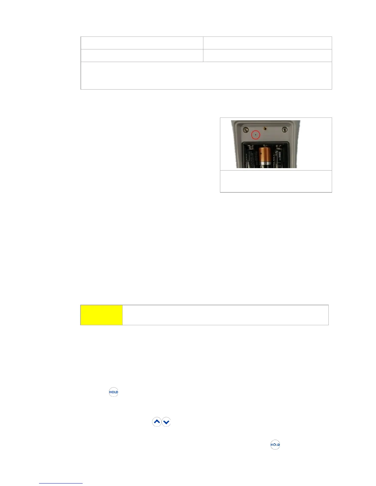
7. Insert the Straightened Paper Clip through
the alignment access hole and gently press
the calibration enable switch located on the
circuit board. See Figure 12 for location.
Voltage Gain and Offset Alignment
8. The UUT display will indicate as follows:
a. Line 1: CAL1
b. Line 2: mV portion of Channel 1
voltage reading
c. Line 3: nV portion of Channel 1 voltage reading
9. Connect the miniature thermocouple connector of the Copper Mini-TC Cable to the
Channel 1 input of the UUT.
a. For two channel UUTs using the Split Copper Mini-TC Cable, connect one
miniature thermocouple connector to the Channel 1 input of the UUT,
and the other connector to the Channel 2 input.
10. Connect the opposite end of the Copper Mini-TC Cable (or Split Copper Mini-TC
Cable) to the appropriate output connectors of the DC Voltage Source.
11. Allow at least three minutes for the connections to temperature stabilize before
proceeding.
CAUTION
Do not apply voltages greater than 80 mV DC to the UUT inputs. Voltages
greater than 80 mV may damage the instrument.
12. Set the DC Voltage Source to output the first Applied Voltage value in Figure 13
below.
13. Allow the DC Voltage source output to stabilize before proceeding.
14. The UUT will display the current voltage reading.
15. Allow the UUT displayed voltage to stabilize before proceeding.
16. Press UUT to automatically adjust the UUT voltage reading to the Applied
Voltage, ±0.001 mV.
a. If the UUT displayed voltage is not within ±0.001 mV of the Applied
Voltage, press until the UUT displayed voltage is within ±0.001
mV, adjusting as close to the Applied Voltage as possible.
b. If the UUT displayed voltage is too far from nominal, may not
function as expected. The UUT will typically indicate 8999 or -999 in this
Figure 12: Alignment Access
Hole Location
 Loading...