AA
audio conFiGurationinitial Set up & audio connectionS audio connectionS (cont.)
rack MountinG
1. Install the VOLT in your equipment rack using the 4 supplied screws. If only two screws are used
for installation, they MUST be installed in the bottom holes (A) of the rack ears. As a best practice,
leave a blank space above and below the unit for proper ventilation and cooling.
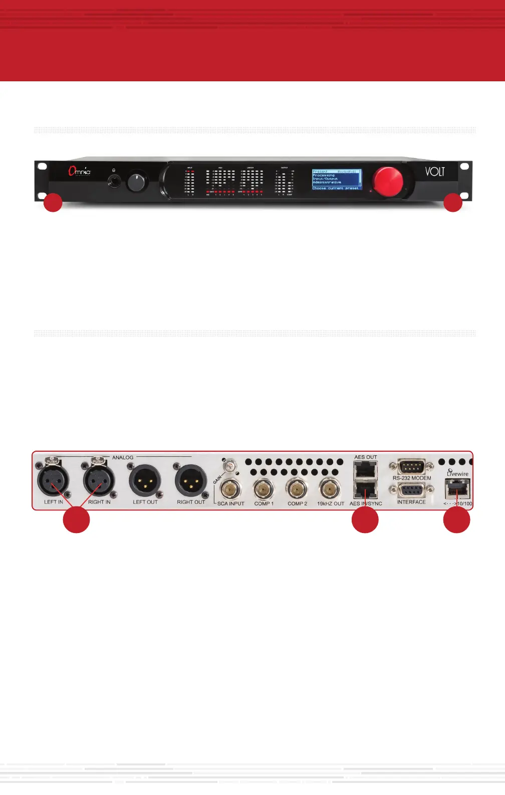
a. For balanced line-level analog audio, connectXLRaudiocablestotheANALOGLEFTINandRIGHTIN
jacks (B).
b. For AES digital audio, connectthedualfemaleXLR“StudioHub”adaptorcableprovidedtothe
RJ-45AESIN/SYNCjack(C).
c. For an existing Axia or Livewire system, connect an Ethernet cable from the Livewire network to the
Livewire jack (D).
audio connectionS
1. Determine the inputs and outputs that are appropriate for your installation.
AUDIO INPUT - Both analog and digital input sources may be connected simultaneously, however, only the
input source that has been selected in the Input menu will be active. For the SG, these should originate from
an external FM audio processor and ideally should be pre-emphasized and fully band limited to 16kHz.
B C D
a. For balanced line-level analog, connectXLRaudiocablestotheANALOGLEFTOUTandRIGHTOUT
jacks (E).
b. For Digital audio, connectthemaleXLR“StudioHub”adaptorcableprovidedtotheRJ-45AESOUTjack(F).
c. For an existing Axia or Livewire system, the single Livewire Ethernet connection made in the input setup
is all that is needed for audio I/O (D).
E
F
DG
continue to audio conFiGuration
The initial set-up of your Omnia VOLT is complete and ready to be configured.
Continue to the "Audio Configuration" instructions.
J
I
input conFiGuration
The Omnia VOLT can be set up directly from the front panel. Note that all of front panel functions, and more,
can also be accessed via password protected login from networked computers, tablets or smartphones.
For instructions on how to configure via networked devices, please refer to the Remote Control chapter in
the Omnia VOLT manual.
J K
1. Navigating input configuration on the front panel is simple and intuitive. Rotate the red jog wheel (K) to scroll
throughoptionsdisplayedontheLCDscreen(J),increase/decreasenumericoptionsandmore.Press the jog
wheel (K) to make a navigation selection or to enter settings.
2. From the front LCD screen, rotatetheredJogwheeluntilDiscreteI/Oishighlighted.Press the jog wheel
in to select.
3. Rotate the jog wheel until Input is highlighted. Press to select.
4. Rotate the jog wheel until Input Src is highlighted. Press to select.
5. Rotate the jog wheel to select the appropriate input source. Press to select.
6. Feed regular program material at your station’s normal level. Tones are not needed for calibration.
Note: On the front panel, only the input and output meters function. There is no multiband processing
on the SG version.
2. Connect the Omnia VOLT to AC Mains (H) using
the AC power cable supplied. Make sure the power
source is properly grounded. There is no power
switch.
3. Once power is supplied, a red power indicator (I)
nexttotheLCD(J)willlightup.TheLCDwillremain
dark for about 25 seconds, then will display “Omnia
VOLT” as the startup sequence progresses. A few
seconds later, the main menu will be displayed.
a. ConnectoneofthecompositeMPXBNCoutputs(G)toyourFMexciterorcompositeSTLtransmitter.
The 2 outputs are separately adjustable so if needed, you can connect the other output to your backup
transmitter as well.
COMPOSTE MPX OUTPUT – Two separately adjustable BNC outputs are available.
AUDIO OUTPUT - All outputs are active simultaneously. The analog XLR, AES/EBU and Livewire outputs
are discrete outputs that can be used for monitoring or relaying to another stereo generator. The outputs
are just monitors of the input. They are not decoded from the composite signal, so they do not reflect
composite clipping, etc. They do have level adjustments and the option to apply de-emphasis.
 Loading...