00053678.DOC, Version 1.2
22/28
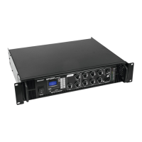
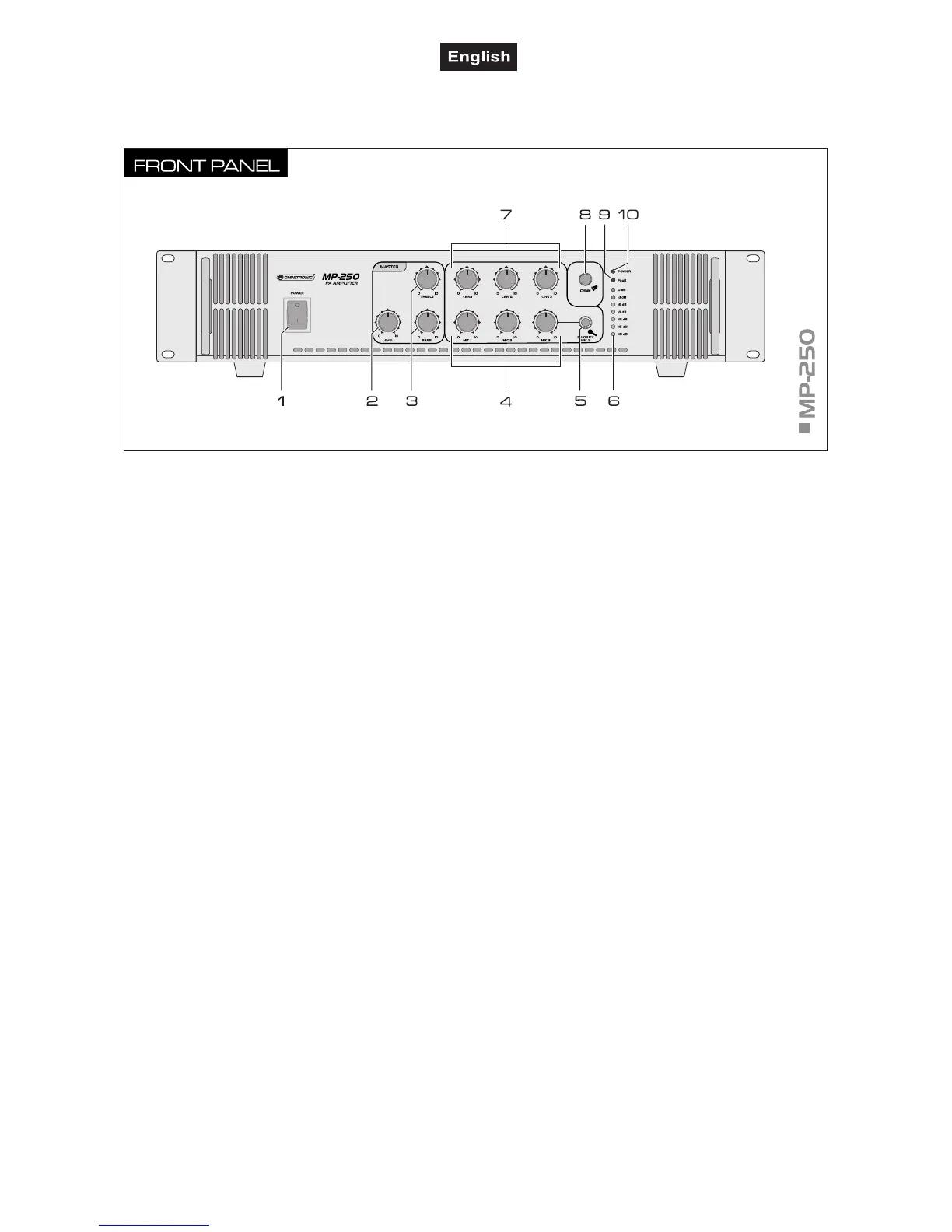
5.2 Operating elements and connections
This user manual describes the MP-250 as a reference. The other models are similar in construction.
Power on/off
Turns the unit on and off. The power indicator lights up
when the unit is powered on.
2 Control LEVEL
Master control for the total volume.
3 Tone controls
2-way tone control for the output signal: bass and treble.
4 Controls MIC 1 to 3
Volume controls for the microphone inputs MIC 1 to 3.
5 Input PRIORITY MIC 3
6.3 mm jack for connecting a dynamic microphone. This
input has priority: In case of an announcement via this
microphone channel the level of the other signal sources
is attenuated–depending on the rear control PRIORITY
LEVEL–thereby increasing the intelligibility of the
announcement.
LED level meter for the output signal
7 Controls LINE 1 to 3
Volume controls for the line inputs LINE 1 to 3.
8 Button CHIME
For releasing the chime.
9 LED FAULT
Lights up with activated protective circuit:
• for a few seconds after switching-on unit the speaker
outputs are ready for operation
• during operation when the protective circuit has
switched off the speakers in case of a defect
10 Power LED
 Loading...