Option Board Description
The 3G3AX-MX2-EIP-A is an option board which can be attached to an
MX2-A□ series inverter. The 3G3AX-MX2-EIP-A allows controlling,
monitoring and parameterization of the inverter via an EtherNet/IP
network. The application in the system that acts as an EtherNet/IP master
is responsible for correct behaviour of the system. The 3G3AX-MX2-EIP-A
is a gateway that passes the communicated register values from the
EtherNet/IP network to the inverter and vice versa.
MX2 Inverter Support
Install the module. The drive firmware version can be read from the web
pages of the module using any web browser. If the version is 43.09, only
limited functionality is available. If the version is 43.23 or higher, there is
full compatibility.
MX2 Inverter Safety (ISO 13849-1)
MX2-A□ inverters provide the Gate Suppress function to perform a safe
stop according to the EN60204-1, stop category 0. The option board has
been designed not to interfere with this safety function.
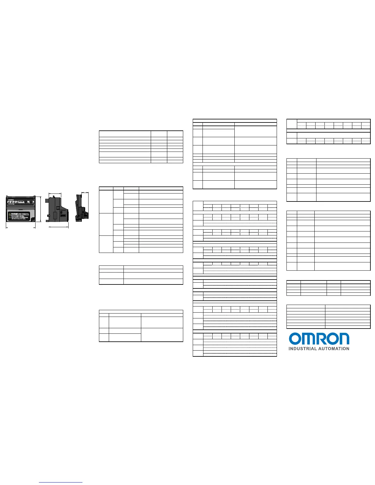
External Dimensions
External dimensions of the option board, shown in millimeters:
Installation Procedure
Follow the next steps to install a 3G3AX-MX2-EIP-A on an MX2-A□ series
inverter:
1. Power down the inverter
2. Loosen the screw of the option board cover on the inverter, remove
the cover and put the cover aside
3. For inverters up to 4.0 kW only: loosen the screws of the terminal
block cover and remove the cover to enable access to the chassis
ground terminal screws
4. Connect the grounding cable to the chassis ground of the inverter
(located on the cooling fin)
5. If removed, mount the terminal cover again and tighten the screw(s)
6. Push the 3G3AX-MX2-EIP-A option board into the previous location
of the option board cover until it clicks into place
7. Tighten the screw of the option board (do not over-tighten).
8. Select the right warning language from the warning label sheet and
replace the English warning if appropriate.
9. To assign an IP address, set the rotary switches (see chart for IP
Settings Rotary Switches) and power up the inverter, the network
and the PLC or EtherNet/IP master unit. For other option board
related inverter parameters see below
EDS File and CX-Integrator
OMRON provides a series of EDS files for the 3G3AX-MX2-EIP-A option
board via the OMRON website. For each of the MX2 inverter type there is
a unique EDS file, which is named:
3G3AX-MX2-EIP-□-E.eds
□ indicates the specific inverter type, such as A4150 or AB004_A2004.
Use these EDS files in the EtherNet/IP master configuration program used
to configure your EtherNet/IP master.
Network Configurator for EtherNetIP in the CX-One Suite is the
configuration program for OMRON EtherNet/IP masters. Start the
configurator and select the Tools/EDS File/Install menu item. Select the
EDS file(s) to start using the 3G3AX-MX2-EIP-A together with OMRON
EtherNet/IP masters.
Supported Modules and I/O Register Layout
The 3G3AX-MX2-EIP-A supports the modules as listed in the EDS file.
The table below shows which modules can be connected.
assembly
Basic Speed IO 20 70
Extended Speed IO (default) 21 71
Extended Speed and Torque Control 123 173
Special IO 100 150
Extended Control IO 101 151
Extended Control IO and Multi function IO
monitor
101 153
Flexible format 139 159
Extended Speed and Acceleration Control 110 111
The EtherNet/IP master can be the source of either frequency reference or
run command. The selected modules influences the required source
selection. See the section below about Option Board Related Inverter
Parameters.
LED Indicators
MS
(Module
Status)
Green Lit Normal operating status
Flashing No I/O connection
I/O connection in IDLE
Red Lit Unit hardware error
Unsupported inverter version.
Flashing Recoverable fault. Consult manual.
--- Not lit Power is not supplied to the Slave
Unit. The Unit is being reset.
NS
(Network
Status)
Green Lit CIP connection established, no
Exclusive owner connection timed out
Flashing IP address configured but no CIP
connection established
Red Lit Duplicate IP address detected
Flashing Exclusive owner connection timed out
--- Not lit No IP address configured
Power supply is OFF.
LA1, LA2
(Link
Activity
1,2)
Green Lit Link established, 100 Mb
Flickering Activity, 100 Mb
Yellow Lit Link established, 10 Mb
Flickering Activity, 10 Mb
--- Not lit No link established
Power supply is OFF
IP Settings Rotary Switches
P185 = 0 Use internally saved IP configuration.
P185 = 1 - 127 The value of P185 sets the last byte (xxx) of the IP
address (192.168,250.xxx)
P186=1 Restores the module to default settings. Set P186 to
1, cylce power, P186 will auto change back to 0
Option Board Related Inverter Parameters
Various inverter parameters influence the behaviour of the option board.
The table below shows these parameters. Please note that most
parameter changes require a power cycle of the inverter or a restart of the
option board.
Network Related Parameters
P044 Communication watchdog
timer while running.
Note: additional to
Ethernet/IP inactivity timer.
0 to 9999 in 0.01 s units. Set 0 to
disable.
Action is defined in P045.
P045 Action on Network Error
Set to 0 for inverter trip (default)
Set to 1 for deceleration and trip
Set to 2 for no action
Set to 3 for stop due to free-run
Set to 4 for deceleration and stop
P048 Action on Network Idle
Mode
Source Selection Parameters
A001 Motor 1 Frequency Source Set to 3. Control determined from
network by control bits NetCtrl and
NetRef.
Set to 4: Network control forced
A002 Motor 1 Run Command
Source
P033 Torque Command Source For option board as source:
Set to 6 if not flexible format
Set to 3 if flexible format
P036 Torque Bias Mode
For option board as source:
Set to 5 if not flexible format
Set to 0 if flexible format
C021 Output Terminal 11 Source Set to 63 for option board as source
C022 Output Terminal 12 Source Set to 63 for option board as source
C028 Analog Output AM Source Set to 16 for option board as source
Option Board Behaviour Related Parameters
C102 Reset Mode Selection Set to 3 for resetting trip only
P160
-
P169
Output Register 1 to 10
contents
Modbus register mapped into
flexible output word 1 to 10
P170
-
P179
Input Register 1 to 10
contents
Modbus register mapped into
flexible input word 1 to 10
IO Assembly Object Allocation
The following table shows the I/O allocation for the main assemblies.
Instance ID 20: Basic Speed Control Output
n - - - - - RST - FWD
- - - - - - - -
n + 1 Rotational Speed Reference (default [0.01 Hz])
Rotational Speed Reference
70: Basic Speed Control Input
n - - - - - DFR - FLT
- - - - - - - -
n + 1 Rotational Speed Monitor (default [0.01 Hz])
Rotational Speed Monitor
Instance ID 21: Extended Speed Control Output
n - REF CTR - - RST REV FWD
- - - - - - - -
n + 1 Rotational Speed Reference (default [0.01 Hz])
Rotational Speed Reference
Instance ID 71: Extended Speed Control Input
n ARF RFN CFN RDY DRR DFR WR FLT
Drive Status (see below)
n + 1 Rotational Speed Monitor (default [0.01 Hz])
Rotational Speed Monitor
Instance ID 123: Extended Speed and Torque Control Output
n/n+1 See instance ID 21
n + 2 Torque Reference [1 %]
Torque Reference
Instance ID 173: Extended Speed and Torque Control Input
n/n+1 See instance ID 71
n + 2 Torque actual [1 %]
Torque actual
Instance ID 101: Extended Control Output
n - CI7 CI6 CI5 CI4 CI3 REV
n + 1 Rotational Speed Reference (default [0.01 Hz])
Rotational Speed Reference
n + 2 Torque Reference [1 %]
Torque Reference
n + 3 Torque Compensation Bias [1 %]
Torque Compensation Bias
Instance ID 151: Extended Control Input
- -
n + 1 Rotational Speed Monitor (default [0.01 Hz])
Rotational Speed Monitor
n + 2 Torque actual [1 %]
Torque actual
n + 3 Output current monitor [0.1 A]
Output current monitor
Instance ID 153: Extended Control Input + Multi Function Input
n + 3
See instance ID 151.
n + 4 - MI7 MI6 MI5 MI4 MI3 MI2 MI1
- - - - - - - -
Output bits
FWD Forward/Stop 0: Stop 1: Forward
REV Reverse/Stop 0: Stop 1: Reverse
RST Fault Reset Reset Fault/Trip condition on transition from
0 to 1
REF NetRef Speed reference selection.
0: Setting of A002 1: Network controlled
CTR NetCtrl Run command selection.
0: Setting of A001 1: Network controlled
FFL Force Fault Force external fault/trip from network
CI3 to
CI7
Control
/Override Input
0: Reset 1: Set override for Multi Function
input 3 to 7
CO1,
CO2,
CR
Set (Relay)
Output
0: Reset 1: Set Multi Function output 1 to 2 or
Relay Output (CR)
Input bits
FLT Fault 0: Normal 1: Fault/Trip
WR Warning 0: Normal 1: Warning
DFR During
forward run
0: Stop/reverse 1: During forward run
DRR During
reverse run
0: Stop/forward 1: During reverse run
DZS During zero
speed
0: Non-zero speed 1: During zero speed.
RDY Inverter
ready
0: Inverter not ready 1: Inverter ready
CFN Ctrl from Net
Run command input selection
0: Local 1: EtherNet/IP reference
RFN Ref from Net
Speed reference input selection
0: Local 1: EtherNet/IP reference
ARF At reference
0: Accel/decel phase 1: At reference
M
MI7
Monitor
inputs 1 to 7
0: OFF 1: ON
MO1,
MO2,
MR
Monitor
(Relay)
outputs
0: OFF 1: ON
Drive Status (for instance ID 71 and 173)
1 Startup 5 Stopping
2 Not ready 6 Fault/Trip Stop
3 Ready 7 Faulted/Tripped
4 Enabled
General Specifications
EtherNet/IP Specification Designed for conformance.
EtherNet/IP Profile AC Drive (0x02)
Autonegotiation 10/100 Mbps
Ambient operating temperature See MX2 inverter User’s Manual
Ambient operating humidity See MX2 inverter User’s Manual
Storage temperature -20 ºC to 65 ºC
Weight 170g
OMRON
OMRON INDUSTRIAL AUTOMATION
1 Commerce Drive,
Schaumburg, IL 60173, U.S.A.
Tel: 847-843-7900
Note: Specification is subject to change without notice
28,4
57 ,9
67,6
44,8

 Loading...


