61F-G@
3
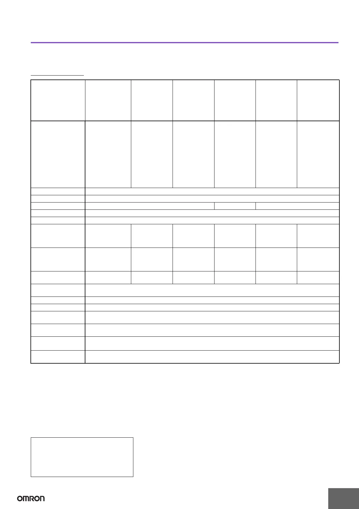
Specifications
■ Standard Models
Specifications
Note: 1. The @ in the model name represents G, G1, G2, G3, G4, and I.
2. The suffix “TDL” attached to the model name represents models designed for tropical regions (storage humidity of 45% to 90%). For
details, refer to Safety Precautions for Floatless Level Controllers.
3. The length when using completely-insulated, 600-V, 3-conductor (0.75 mm
2
) cabtire cables. Usable cable lengths will become shorter as
the cable diameter or number of conductors becomes larger. For details, refer to Safety Precautions for Floatless Level Controllers.
4. The insulation resistance and dielectric strength indicate values between power terminals and Electrode terminals, between power ter-
minals and contact terminals, and between Electrode terminals and contact terminals.
5. Possible to use with 15 kΩ or less, however, this may cause reset failure.
6. High-sensitivity Controllers use advanced operation.
When the power supply voltage is applied, if there are some liquids between the electrodes (ground and operation electrodes), the inter-
nal relay will not operate.
When the power supply voltage is applied, if there are no liquids between the electrodes (ground and operation electrodes), the internal
relay will operate.
Items General-purpose
Controller
61F-@ (TDL)
(see note
1 and 2)
High-
temperature
Controller
61F-@T
(see note 1)
Long-distance
Controllers
61F-@L 2KM
(for 2 km)
61F-@L 4KM
(for 4 km)
(see note 1)
High-sensitivity
Controllers
61F-@H
(see note 1)
Low-sensitivity
Controller
61F-@D
(see note 1)
Two-wire
Controller
61F-@R
(see note 1)
Controlling materials
and operating condi-
tions
For control of ordi-
nary purified water
or sewage water
For control of ordi-
nary purified water
or sewage water
in cases where the
ambient tempera-
ture is high.
For control of ordi-
nary purified water
in cases where the
distance between
sewage pumps
and water tanks or
between receiver
tanks and supply
tanks is long or
where remote
control is required.
For control of liq-
uids with high
specific resis-
tance such as dis-
tilled water
For control of liq-
uids with low spe-
cific resistance
such as salt water,
sewage water,
acid chemicals, al-
kali chemicals
For control of ordi-
nary purified water
or sewage water
used in combina-
tion with Two-wire
Electrode Holder
(incorporating a
resistor of 6.8 kΩ)
It is possible to wire
with less than one
wiring against gen-
eral 61F’s wiring.
Supply voltage 100, 110, 120, 200, 220 or 240 VAC; 50/60 Hz
Operating voltage range
85% to 110% of rated voltage
InterElectrode voltage 8 VAC 24 VAC 8 VAC
InterElectrode current Approx. 1 mA AC max.
Power consumption 61F-G@: 3.5 VA max.; G1F-G1@, G1F-G2@, or G1F-I@: 5.5 VA max.; G1F-G3@: 7.5 VA max.; G1F-G4@: 14.5 VA max.
InterElectrode operate
resistance
0 to approx. 4 kΩ 0 to approx. 5 kΩ 0 to approx.
1.8 kΩ (for 2 km)
0 to approx.
0.7 kΩ (for 4 km)
Approx. 15 kΩ to
70 kΩ
(see note 5)
0 to approx.
1.8 kΩ
0 to approx. 1.1 kΩ
InterElectrode release
resistance
Approx. 15 k to ∞Ω Approx. 15 k to
∞Ω
4 k to ∞Ω (for
2km)
2.5 k to ∞Ω (for
4km)
Approx. 300 k to
∞Ω
Approx. 5 k to ∞Ω Approx. 15 k to
∞Ω
Cable length
(see note 3)
1 km max. 600 m max. 2 km max.
4 km max.
50 m max. 1 km max. 800 m max.
Control output 2 A, 220 VAC (Inductive load: cosφ = 0.4)
5 A, 220 VAC (Resistive load)
Ambient temperature Operating: –10 to 55°C (–10 to 70°C for 61F-@T)
Ambient humidity Operating: 45% to 85% RH
Insulation resistance
(see note 4)
100 MΩ min. (at 500 VDC)
Dielectric strength
(see note 4)
2000 VAC, 50/60 Hz for 1 min.
Life expectancy Electrical: 500,000 operations min.
Mechanical: 5,000,000 operations min.
Weight 61F-G@: Approx. 380 g, G1F-G1@, G1F-G2@, or G1F-I@: Approx. 750 g;
G1F
-G3@: Approx. 930 g;
G1F-G4@: Approx. 1,710 g
• Advanced Operation
With advanced operation, the internal relay
operates as soon as control power is
supplied to the G1F and is reset when current
flows between the poles. Wiring is the same
as for models with sequential operation.
 Loading...


