61F-G@
7
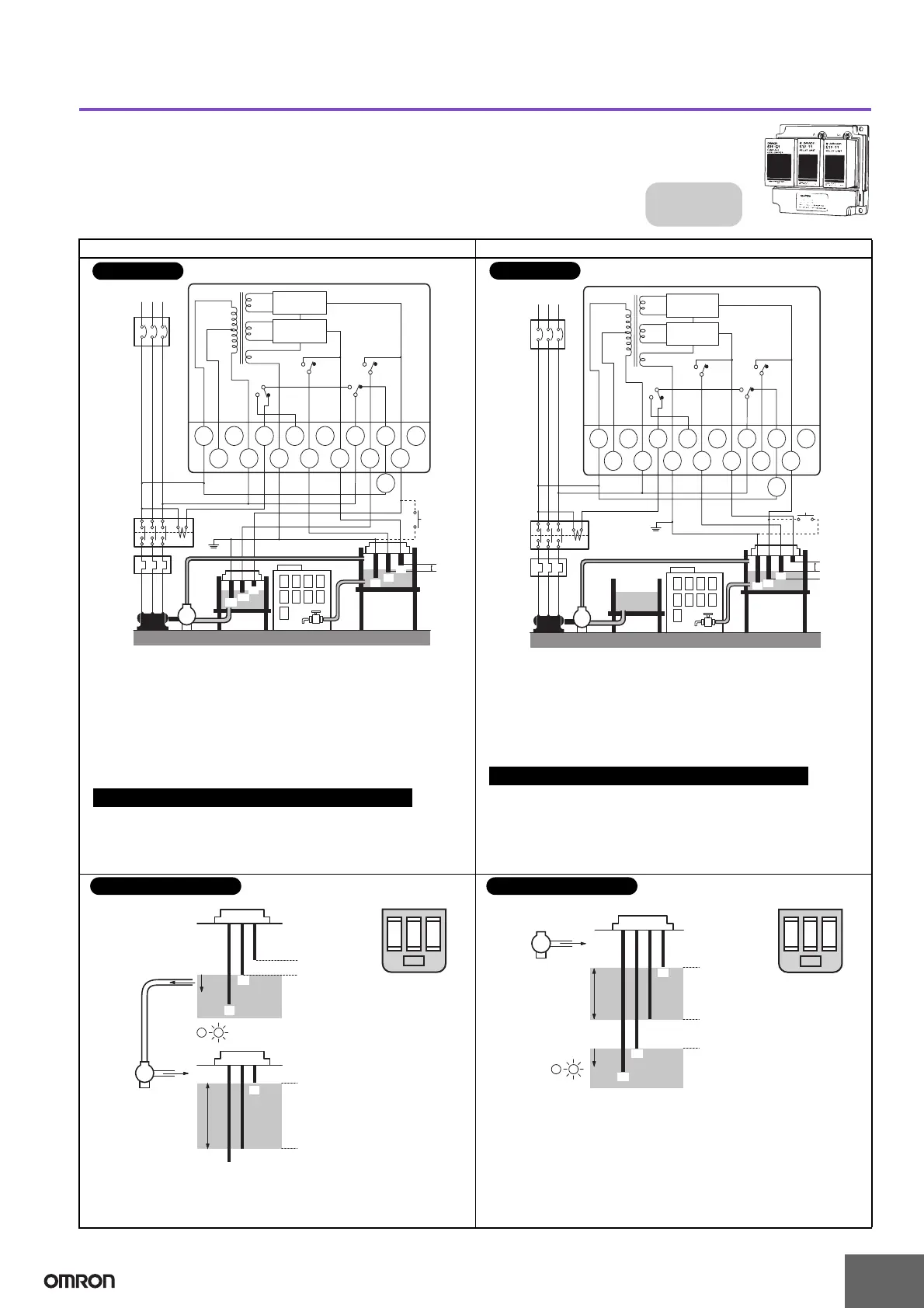
Automatic Water Supply Control with Pump Idling Prevention
Automatic Water Supply Control with Abnormal Water Shortage Alarm
Basic Type
61F-G1
Dimensions:
page 14
Automatic Water Supply Control with
Pump Idling Prevention and Automatic
Water Supply Control with Abnormal
Water Shortage Alarm
U1
U1
U2
U1
U2
U2
Contactor
Water
supply
source
Motor
protection
relay
MCCB
RS
M
T
220 VAC power supply
61F-G1
Water
tank
PS-3S
(See note.)
S
o
T
b1
T
a1
T
c2
T
b2
S
1
S
2
E
3
E
2
E
1
E
2
'E
1
'
E
2
E
3
PS-3S
E2'
E
3'
E
1'
P
61F-11
Relay Unit
8 V
220 V
110 V
0 V
24 V
24 V
61F-11
Relay Unit
(E
4
)
Alarm
B
Push
button
switch
Stop
Start
E
1
Note: Be sure to ground the common Electrode (the longest Electrode).
• Power Supply Connections
110 VAC: Connect S
0
and S
1
.
220 VAC: Connect S
0
and S
2
.
• Insert a pushbutton switch (NO) between E
1
' and E
3
, as shown by
the dotted lines above.
• Do not press the pushbutton if the low-water alarm sounds and
the pump stops during normal operation (U
1
indicator ON, water
below E
2
').
If the supply water level is below E
1
' when starting operation or
when recovering from a power interruption, press the pushbutton to
momentarily close the circuit (U
1
indicator turns ON) to start the
pump.
Test Operation/Recovering from Power Interruptions
Connections
U
1
U
1
U
2
U
1
U
2
U
2
Water supply
source
MCCB
RS
M
T
220 VAC power supply
61F-G1
Water
tank
PS-4S
(See note.)
S
o
T
b1
T
a1
T
c2
T
b2
S
1
S
2
E
3
E
2
E
1
E
2
'E
1
'
E
3
P
61F-11
Relay Unit
8 V
220 V
110 V
0 V
24 V
24 V
61F-11
Relay Unit
(E4)
Alarm
B
Push
button
switch
Stop
Start
Water
shortage
E
2
E
4
E
1
Contactor
Motor
protection
relay
Note: Be sure to ground the common Electrode (the longest Electrode).
• Power Supply Connections
110 VAC: Connect S
0
and S
1
.
220 VAC: Connect S
0
and S
2
.
• Insert a pushbutton switch (NO) between E
3
and E
4
.
• If the pump stops when the pushbutton switch is released, press
it again.
If the supply water level is below E
4
when starting operation or
when recovering from a power interruption, press the pushbutton
to momentarily close the circuit (U
1
indicator turns ON) to start the
pump.
Test Operation/Recovering from Power Interruptions
Connections
E
1
'
E
2
'
E
3
E
1
BL
E
2
E
3
P
Water tank
Water supply source
Water
supply
Water
shor-
tage
(U
1
indicator ON)
Pump OFF
Pump ON
(U
1
indicator OFF)
(U
2
indicator ON)
(U
2
indicator OFF)
• The pump starts (U
2
indicator OFF) when the water level drops below E
2
and stops (U
2
indicator ON) when the water level reaches E
1
.
• When the level of the water supply source drops below E
2
', the pump
stops (U
1
indicator OFF). Pump idling is prevented and the alarm sounds.
Relay Unit Location
Principles of Operation
E1
E2
E4
E3
P
Water tank
Water
supply
Water
shor-
tage
(U2 indicator ON)
Pump OFF
Pump ON
(U
1 indicator OFF)
(U2 indicator OFF)
BL
U
1
U
2
Powe r
supply
• The pump stops (U
2
indicator ON) when the water level reaches E
1
and
starts (U
2
indicator OFF) when the water level drops below E
2
.
• If the water level drops below E
4
for any reason, the pump stops (U
1
indicator OFF) and the alarm sounds.
Relay Unit Location
Principles of Operation
 Loading...


