ATEG Automation GmbH
|
Intzestraße 50
|
42859 Remscheid
|
Germany
|
Tel.: +49 (0)2191 / 591457-0
|
info@ateg.de
|
www.ateg.de
Datenblatt
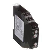
Zeitrelais H3DT
H3DT
H3DT-N/H3DT-L
6
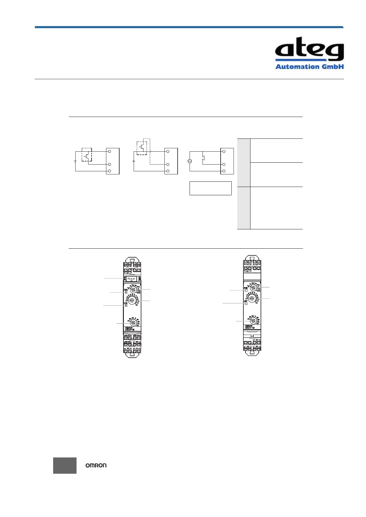
Input Connections
The start input is a voltage input.
Nomenclature
Sensor
Timer
A1 (+)
A2 (−)
B1
Start
24
VDC
24 VDC
(sensor
power supply)
(+)
(−)
Sensor
Timer
A1 (−)
A2 (+)
B1
Start
24
VDC
(−)
(+)
Timer
A1
A2
B1
Start
Operates when PNP transistor turns ON. Operates when NPN transistor turns ON. Operates when relay turns ON.
24 VDC
(sensor
power supply)
Voltage Input Signal Levels
Tran-
sistor
input
1. Transistor ON
• Residual voltage: 1 V max.
Voltage between terminals B1
and A2 must be equal to or
higher than the rated high level
voltage (20.4 VDC min.).
2. Transistor OFF
• Leakage current: 0.01 mA max.
Voltage between terminals B1
and A2 must be equal to or
below the rated low level voltage
(2.4 VDC min.).
Relay
input
Use relays that can adequately
switch 0.1 mA at the imposed
voltage.
When the relay is ON or OFF, the
voltage between terminals B1 and
A2 must be within the following
ranges:
• 24 to 240 VAC/DC
When relay is ON: 20.4 to 264
VAC/DC
When relay is OFF: 0 to 2.4 V
PNP Transistor Input NPN Transistor Input Relay Input
Consider the minimum load
of the relay. (See signal
levels on the right.)
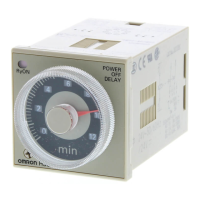
Time range switch *
* If the switch is left between settings, proper operation may not be possible.
Make sure that the switch is set properly.
Note: The default settings are for 0.1 s in mode A2 for the H3DT-N and mode A for the H3DT-L.
Output indicator (orange)
(Lit while Timer gives output.)
Operating mode switch *
INIT/TIME switch for relay R2
(Default setting is for time-limit output.) *
Main dial
(for setting the time)
Operation/power indicator (green)
(Flashes while Timer is operating.
Lit when Timer is stopped.)
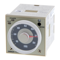
Time range switch *
* If the switch is left between settings, proper operation may not be possible.
Make sure that the switch is set properly.
Note: The default settings are for 0.1 s in mode A2 for the H3DT-N and mode A for the H3DT-L.
Output indicator (orange)
(Lit while Timer gives output.)
Operation/power indicator (green)
(Lit while the power is ON.)
Operating mode switch *
Main dial
(for setting the time)
Erstellt am 09.10.2020 um 23:38 Uhr | Alle Angaben ohne Gewähr, Irrtümer und Änderungen vorbehalten! Seite 7 von 37
 Loading...