29
1, 2, 3... 1. I/O Unit Lock Notch
The lock notch fits into the Backplane to hold the Unit in place.
2. Nameplate
The nameplate shows the model number of the I/O Unit.
3. I/O Indicators (LED)
The indicators show the ON/OFF status of the I/O points. The arrangement
of the indicators varies with the model of I/O Unit, as shown in the following
tables.
4. I/O Number Setting Switch
This switch is used to set the I/O number for the Unit. Set the number to
between 0 and F for Units with one 40-pin connector and to between 0 and 8
or A and E for Units with two 40-pin connectors.
5. 40-pin Connectors
The number of connectors depends on the Unit.
6. Indicator Switch
Determines whether the status of connector 1 or connector 2 I/O points are
shown on the I/O indicators.
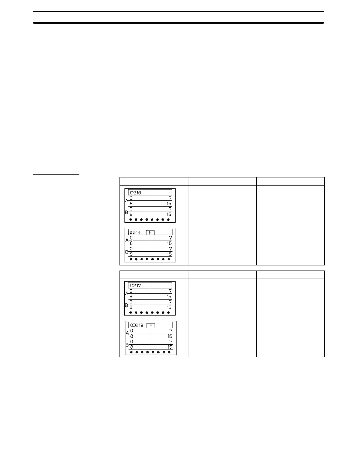
I/O Indicators
Appearance Unit type Model numbers
32 points Unit ID216 and ID218
32 points Unit
F: Fuse burnt out
(with LED)
OD218 and OD21B
Appearance Unit type Model numbers
64 points Unit ID111, ID217, and ID219
64 points Unit
F: Fuse burnt out
(with LED)
OD219
Units with One 40-pin
Connector
Units with Two 40-pin
Connectors
Units
Section 2-2
 Loading...


