!
52
Note Tighten the PC Rack mounting screws, terminal block screws, and cable screws
to the torque of 1.2 N S m.
Caution Racks must be mounted horizontally so that the Units are upright (i.e., not upside
down or lying on their backs). The Units can overhead and malfunction if not
mounted properly.
I/O Connecting Cables Each I/O Connecting Cable can be up to 10 m long, but the sum total of all cables
between the CPU Rack and Expansion I/O Racks must be 12 m or less.
The duct work shown in the following diagram is recommended to hold I/O wir-
ing. Although optional, this duct work can be used to house the wires from the I/O
Units that run along the sides of the Racks, keeping the wires from becoming
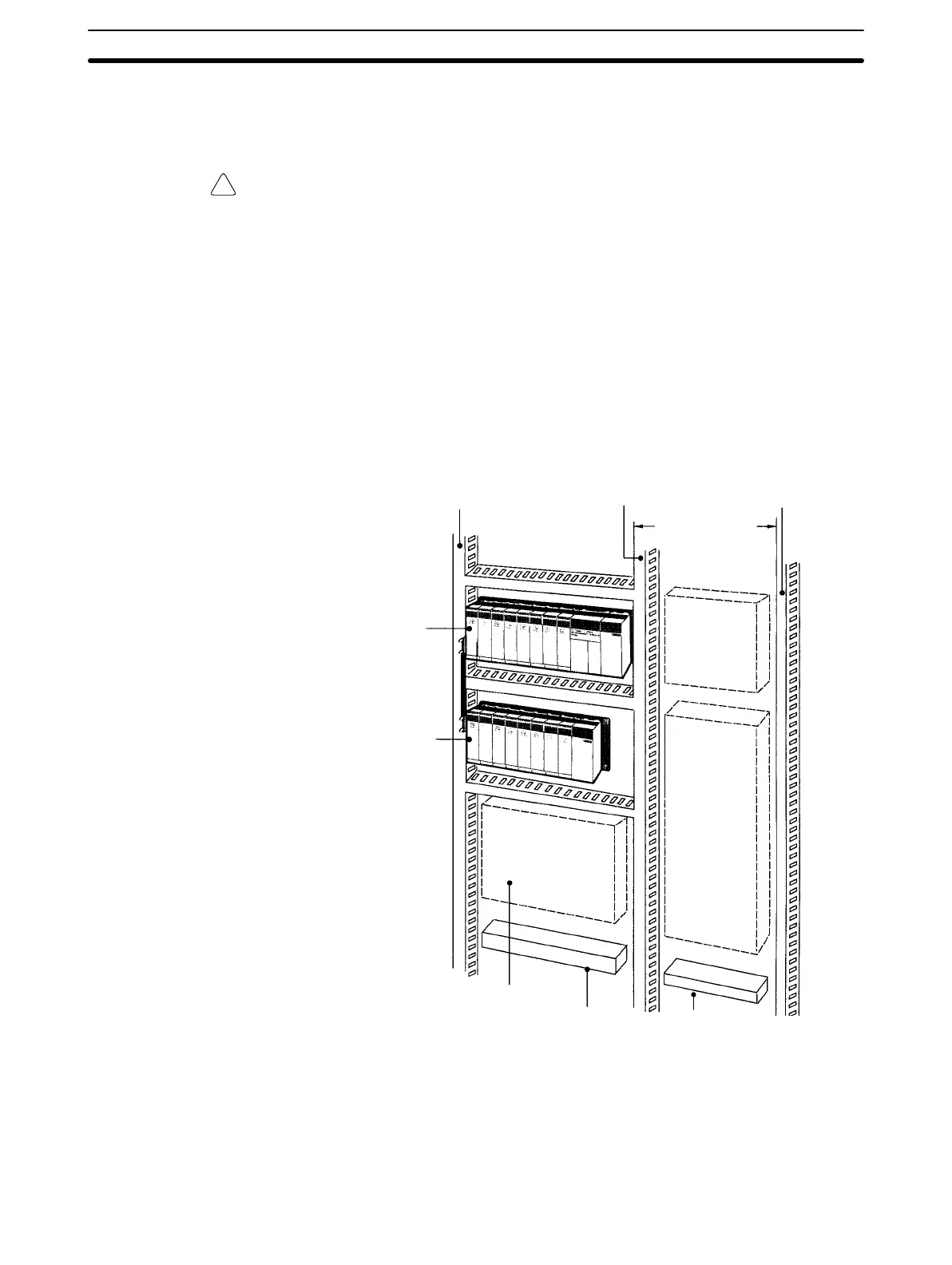
entangled. This figure illustrates the correct way to mount the Racks.
Input duct
CPU
Rack
Expansion
I/O Rack
Power
equipment
such as
transform-
ers and
magnetic
relays
Breakers,
fuses
Output duct
Power duct
200 mm min.
Terminal blocks for
power equipment
Terminal blocks
for PC
Fuses, relays, tim-
ers, etc. (NOT
heat-generating
equipment, power
equipment, etc.)
Note When using the C200HW-PA209R Power Supply Unit at an ambient tempera-
ture exceeding 50°C, in order to improve air circulation, ensure that there is a
Installation Environment Section 3-1
 Loading...


