E3JM
6
Safety Precautions
Refer to Warranty and Limitations of Liability.
This product is not designed or rated for ensuring
safety of persons either directly or indirectly.
Do not use it for such purposes.
Do not use the product in atmospheres or environments that exceed
product ratings.
● Designing
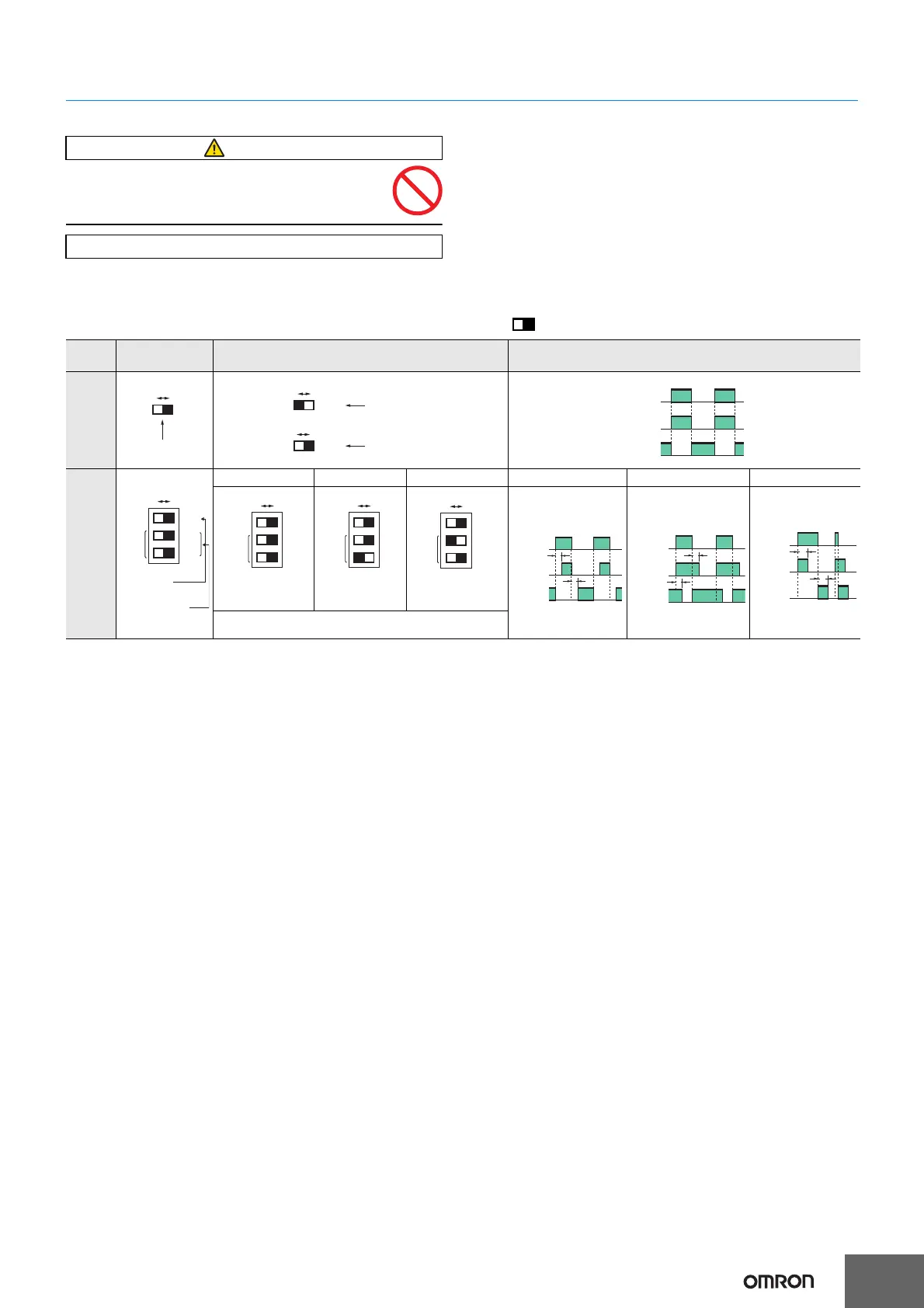
Operation Note: The white part of the DIP switch indicates which setting is selected.
Output Relay Contact
If E3JM is connected to a load with contacts that spark when the load is turned OFF (e.g., a contactor or valve), the normally-closed side may be
turned ON before the normally-open side is turned OFF or vice-versa. If both normally-open output and normally-closed output are used
simultaneously, apply an surge suppressor to the load.
WARNING
Precautions for Correct Use
Switch
configuration
Switch selection Timing charts
Models
without
timer
Models
with
timer
ON-delay OFF-delay One-shot delay ON-delay OFF-delay One-shot delay
Note: The operation selector is the same as that for models
without a timer.
MODE
0 1
D·ON L·ON
Operation
selector
D·ON L·ON
Dark-ON, Relay ON
DC output switching
element ON
D·ON L·ON
Light-ON, Relay ON,
DC output switching
element ON
MODE
0 1
MODE
0 1
Incident light
No incident light
ON
OFF
ON
OFF
L
·
ON
D
·
ON
MODE
0 1
D·ON L·ON
SW1
SW2
TIMER
Operation
Selector
Selector switch for
timer mode
MODE
0 1
D·ON
L
·
ON
SW1
SW2
TIMER
Both SW1 and
SW2 at "0."
MODE
0 1
D·ON
L
·
ON
SW1
SW2
TIMER
Onl
SW2 at "1."
MODE
0 1
D·ON
L
·
ON
SW1
SW2
TIMER
Only SW1 at "1,"
which overrides either
setting of SW2.
L·ON
D
·ON
T
T
Incident light
No incident light
ON
OFF
ON
OFF
L·ON
D
·ON
T
T
Incident light
No incident light
ON
OFF
ON
OFF
L
·
ON
D
·
ON
T
T
Incident light
No incident light
ON
OFF
ON
OFF
 Loading...