E8F
E8F
7
(6) Buzzer Mode Settings
Set the buzzer mode to 0 if the buzzer function is not required.
Note:
The mode is set to 3 before shipping.
Set value
Contents
0 The buzzer is always OFF.
1
The buzzer is ON when the ON/OFF output
transistor is ON.
2
The buzzer is ON when an error is
detected.
3
The buzzer is ON when the Up or Down
Key is pressed when setting the values.
4
The functions of set values 1 and 3.
5
The functions of set values 2 and 3.
Error Indication
LCD Meaning Remedy
E1 The
ON/OFF output and error output transistor have excessive current.
Change the load to a proper one.
E2
No zero point adjustment is possible when the ZERO Key is pressed
because pressure is imposed on the pressure port.
Eliminate the pressure imposed on the pressure
port.
E3 Excessive pressure is imposed on the pressure port.
Reduce the pressure to the rated value or less.
E4 Reversed pressure is imposed.
Do not impose reversed pressure.
E5
The Sensor has a failure.
Contact your OMRON representatives.
E6
The voltage imposed on the Sensor is not within the rated value.
Impose the voltage within the rated value.
Note: 1. If
the load is short-circuited or excessive current flows to the load, the green indicator will flash and the ON/OFF output and error
output
will be turned OFF
.
2. If
there is an error other than a load short-circuit or excessive current error (i.e., E2 to E6), the green indicator will be turned OFF and
the
error output transistor will be turned ON. Therefore, nullify the ON/OFF output at the time of error detection.
Zero Point Adjustment
Usually, no zero point adjustment is necessary. If the zero point
should
shift due to secular changes (i.e., a value other than 00 is dis
-
played with no pressure imposed), press the ZERO Key for zero
point
adjustment.
Perform zero point adjustment with no pressure imposed.
ON/OFF Set Value Check on E8F in Operation
Press
the Up Key to check the ON set value.
Press the Down Key to check the OFF set value.
Mounting
The zinc die-cast
pressure leading part incorporates an R(PT) 1/8
taper
screw and M5 x P0.8 female screw
. The taper screw must be
used
in combination with an Rc(PT) 1/8 female taper screw
.
Apply sealing tape around the taper screw so that there will be no
pressure
leakage. Make sure that the tightening torque of the taper
screw
is 9.8 N
S
m (100 kgf
S cm) or less.
Make sure that the tightening torque of the M5 female screw is
2.3 N
S
m (23 kgf
S cm) or less.
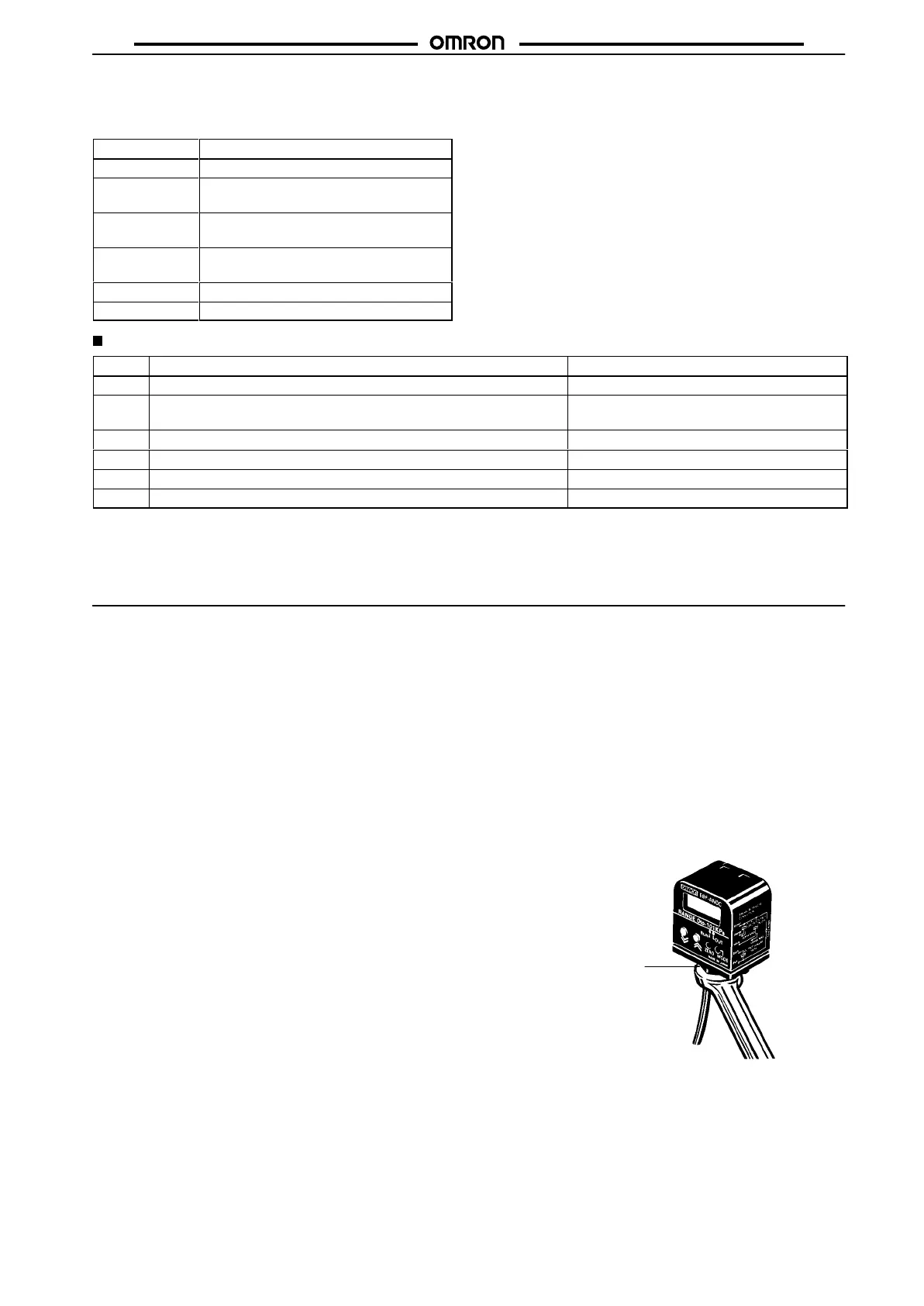
When
tightening the male screw
, apply a 12-mm wrench to the hex
-
agonal
portion of the pressure port. Do not tighten the male screw
while holding the plastic case.
When
attaching the mounting bracket to the E8F
, make sure that the
tightening torque applied to the M2.5 screw is 0.29 N
S
m (3 kgf
S
cm)
or less.
Hexagonal portion
 Loading...