15
H5CRH5CR
Installation
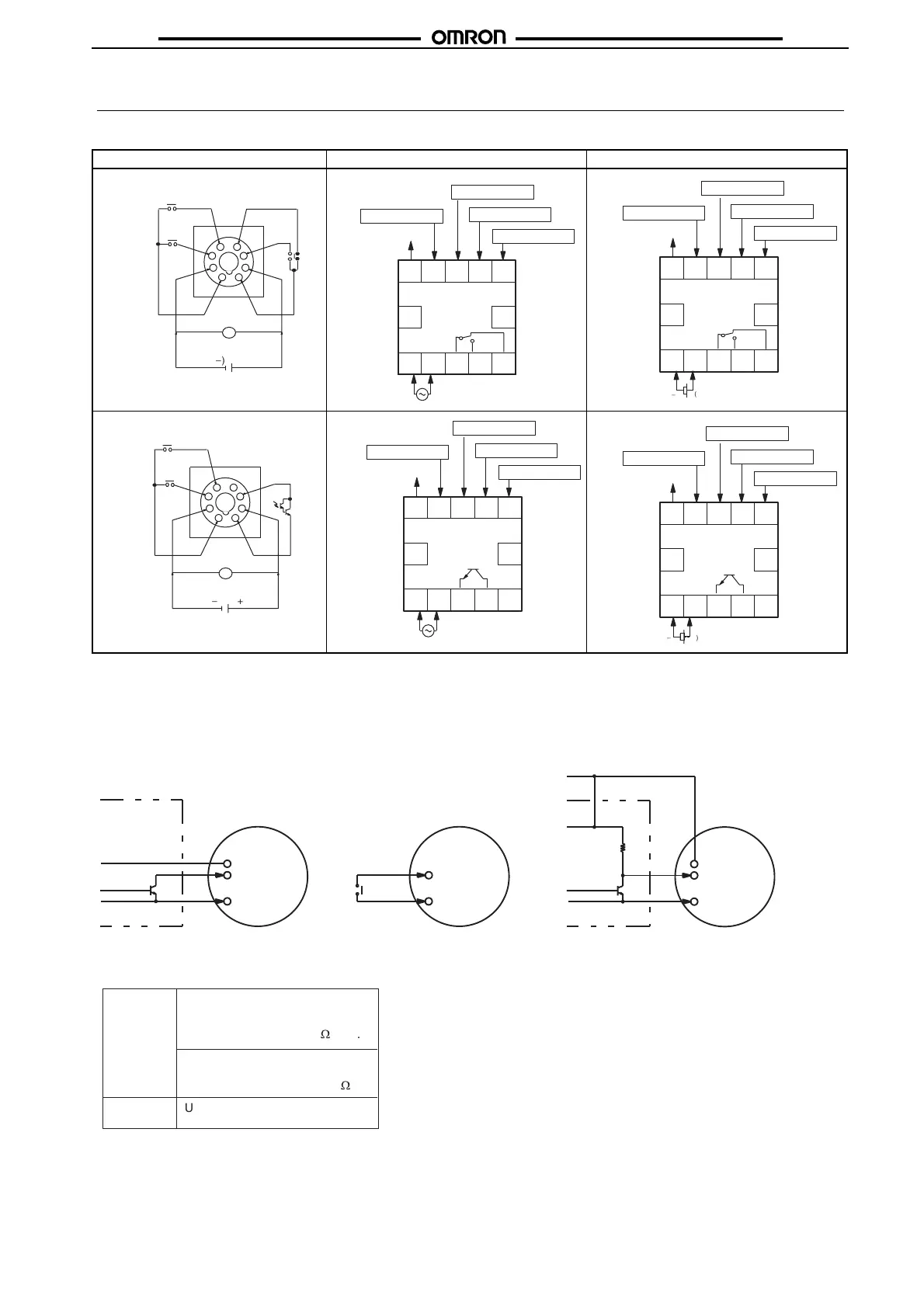
■ Terminal Arrangement
Note: Do not connect unused terminals.
■
Connections
H5CR-L (Basic) H5CR-B (Standard) H5CR-S (Short body)
Contact output
100 to 240 VAC/ 24 VAC
(
-
)(+)
12 to 24 VDC
1
2
3
4 5
6
7
8
0V
Start signal
Reset
11 12
6 7 8 9 10
1 2 3 4 5
Input use 0 V
Reset input
Start signal input
Gate input
Key protect input
OUT
100 to 240 VAC/24 VAC
Contact output
Unused Unused
Contact output
12 to 24 VDC
(
-
)
(+)
11 12
6 7 8 9 10
1 2 3 4 5
Input use 0 V
Reset input
Gate input
Key protect input
OUT
Unused Unused
Start signal input
Transistor output
1
2
3
4
5
6
7
8
Start signal
Reset
0V
100 to 240 VAC/ 24 VAC
(
-
)(+)
12 to 24 VDC
Unused
Transistor output
11 12
6 7 8 9 10
1 2 3 4 5
Input use 0 V
Reset input
Gate input
Key protect input
OUT
100 to 240 VAC/24 VAC
Unused Unused
Start signal input
Transistor output
12 to 24 VDC
(
-
)
(+)
11 12
6 7 8 9 10
1 2 3 4 5
Input use 0 V
Reset input
Gate input
Key protect input
OUT
Unused Unused
Start signal input
The inputs of the H5CR are no-voltage (short circuit or open) inputs.
No-voltage Input Signal Levels
No-contact
input
Contact
input
1. High level
Transistor ON
Residual voltage: 2 V max.
Impedance when ON: 1 k
W
max.
2. Low level
Transistor OFF
Impedance when OFF: 100 k
W
min.
Use contacts which can adequate-
ly switch 2 mA at 5 V
No-contact Input
(NPN Transistor)
Contact Input No-contact Input
Sensor
Timer
High: transistor ON
Timer
High: contact ON High: transistor ON
Sensor
Timer
12 VDC
+V (30 V max.)
Input use 0 V
Start signal,
reset, etc.
12 VDC
Start signal,
reset, etc.
Input use 0 V
Start signal,
reset, etc.
Input use 0 V
 Loading...