6
H7CX-A@-N
Tachometer Function Ratings
* An input OFF time of at least 20 ms is required.
Characteristics
Model
Item
H7CX-A114@-N
H7CX-A11@-N
H7CX-A4@-N
H7CX-A@-N
H7CX-A4W@-N
H7CX-AW@-N/-AU@-N
Input mode
No tachometer
functionality
Selectable from independent measurements for 1 or 2 inputs, differential input for 2 inputs, absolute ratio for 2 inputs, and error ratio
for 2 inputs.
Pulse measurement
method
Periodic measurement Pulse width measurement
Maximum counting
speed
30 Hz
(minimum pulse width: 16.7 ms)
1-input mode:
10 kHz
(minimum pulse width: 0.05 ms)
Other modes:
5 kHz
(minimum pulse width: 0.1 ms)
30 Hz
(minimum pulse width: 16.7 ms)
1-input mode:
10 kHz
(minimum pulse width: 0.05 ms)
Other modes:
5 kHz
(minimum pulse width: 0.1 ms)
Minimum input
signal width
--- --- 30 ms
*1
1-input mode: 0.2 ms
Other modes: 0.4 ms*
Measuring ranges 0.001 to 30.00 Hz
1-input mode: 0.001 to 10 kHz,
Other modes: 0.01 to 5 kHz
0.030 to 999999 s
1-input mode: 0.0002 to 99999 s
Other modes: 0.0004 to 99999 s
Sampling period 200 ms min.
200 ms min. or continuous
selectable (minimum interval of
10 ms)
Continuous (minimum interval of 10 ms)
Measuring accuracy ±0.1% FS ±1 digit max. (at 23 ±5°C)
Output mode
Input mode:
Not 2-input independent measurement: HI-LO, AREA, HI-HI, LO-LO
2-input independent measurement: HI-HI, LO-LO
Auto-zero time 0.1 to 999.9s
Startup time 0.0 to 99.9s
Averaging Simple averaging/moving averaging selectable, Processing: OFF, 2, 4, 8, or 16 times
Hold input Minimum input signal width: 20 ms
* Refer to the Life-test Curve.
Applicable Standards
* The following safety standards apply to models with sockets (H7CX-A11@ or H7CX-A114@).
cUL (Listing): Applicable when an OMRON P2CF(-E) Socket is used.
cUR (Recognition): Applicable when any other socket is used.
Insulation resistance
100 MΩ min. (at 500 VDC) between current-carrying terminals and exposed non-
current-carrying metal parts, and between non-continuous contacts
Dielectric strength
2,000 VAC, 50/60 Hz for 1 min between current-carrying metal parts and non-
current-carrying metal parts
2,000 VAC, 50/60 Hz for 1 min between power supply and input circuit for all models
except H7CX-@D@ (1,000 VAC for 24 VAC/12 to 24 VDC)
1,000 VAC (for H7CX-@SD@), 50/60 Hz for 1 min between control output, power
supply, and input circuit (2,000 VAC for models other than H7CX-@SD@)
1,000 VAC, 50/60 Hz for 1 min between non-continuous contacts
Impulse withstand voltage
3.0 kV between power terminals (1.0 kV for models with 24 VAC/12 to 24 VDC or 12
to 24 VDC)
4.5 kV between current-carrying terminals and exposed non-current-carrying metal
parts (1.5 kV for models with 24 VAC/12 to 24 VDC or 12 to 24 VDC)
Noise immunity
±1.5 kV between power terminals (±480 V for models with 12 to 24 VDC)
±600 V between input terminals
Square-wave noise by noise simulator (pulse width: 100 ns/1 μs, 1-ns rise)
Static immunity
Malfunction: 8 kV
Destruction: 15 kV
Vibration
resistance
Destruction 10 to 55 Hz with 0.75-mm single amplitude each in three directions for 2 h each
Malfunction 10 to 55 Hz with 0.35-mm single amplitude each in three directions for 10 min each
Shock re-
sistance
Destruction 300 m/s
2
each in three directions
Malfunction 100 m/s
2
each in three directions
Life expectancy
Mechanical: 10,000,000 operations min.
Electrical: 100,000 operations min. (3 A at 250 VAC, resistive load, ambient
temperature condition: 23°C)*
Weight Approx. 130 g (Counter only)
Approved
safety
standards
cULus (or cURus): UL508/CSA C22.2 No. 14*
EN 61010-1 (IEC 61010-1): Pollution degree 2/overvoltage category II
B300 PILOT DUTY
1/4 HP 120 VAC, 1/3 HP, 240 VAC, 3 A resistive load
VDE0106/P100 (finger protection)
EMC
(EMI) EN61326
Emission Enclosure: EN 55011 Group 1 class A
Emission AC mains: EN 55011 Group 1 class A
(EMS) EN61326
Immunity ESD: EN 61000-4-2: 4 kV contact discharge;
8 kV air discharge
Immunity RF-interference: EN 61000-4-3: 10 V/m (Amplitude-modulated, 80 MHz to 1
GHz);
10 V/m (Pulse-modulated, 900 MHz ±5 MHz)
Immunity Conducted Disturbance: EN 61000-4-6: 10 V (0.15 to 80 MHz)
Immunity Burst: EN 61000-4-4: 2 kV power-line;
1 kV I/O signal-line
Immunity Surge: EN 61000-4-5: 1 kV line to lines (power and output lines);
2 kV line to ground (power and output lines)
Immunity Voltage Dip/Interruption: EN 61000-4-11: 0.5 cycle, 100% (rated voltage)
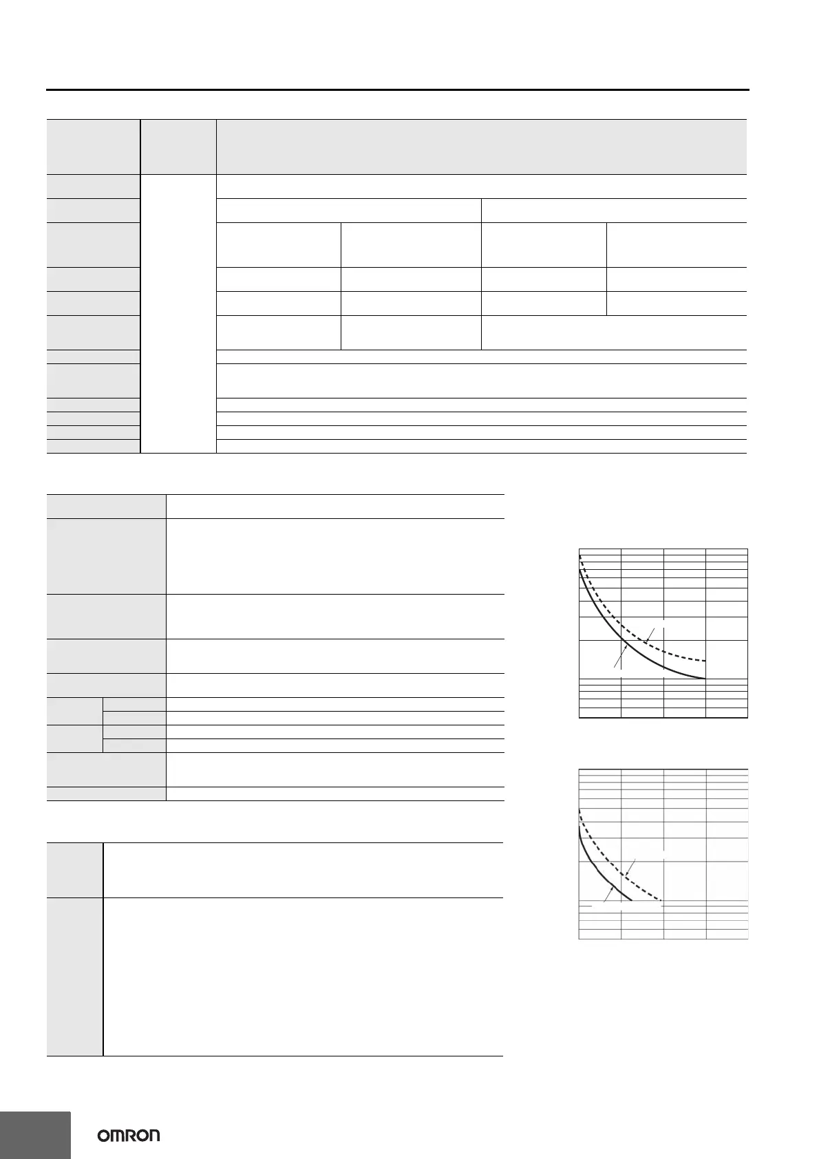
L
e-test
urve
Re
erence
Values)
Resistive load
Inductive load
A current of 0.15 A max. can be switched at 125
VDC (cosφ=1) and current of 0.1 A max. can be
switched if L/R=7 ms. In both cases, a life of
100,000 operations can be expected.
1,000
700
500
300
100
70
50
Load current
A
01 2 34
30 VDC (cosφ=1)
250 VAC (cosφ=1)
No. of operations (
×
10
3
)
1,000
700
500
300
100
70
50
01 2 34
30 VDC (L/R=7 ms)
Load current (A)
250 VAC (cosφ=1)
No. of operations (
×
10
3
)

 Loading...


