H7CX-A@-N
8
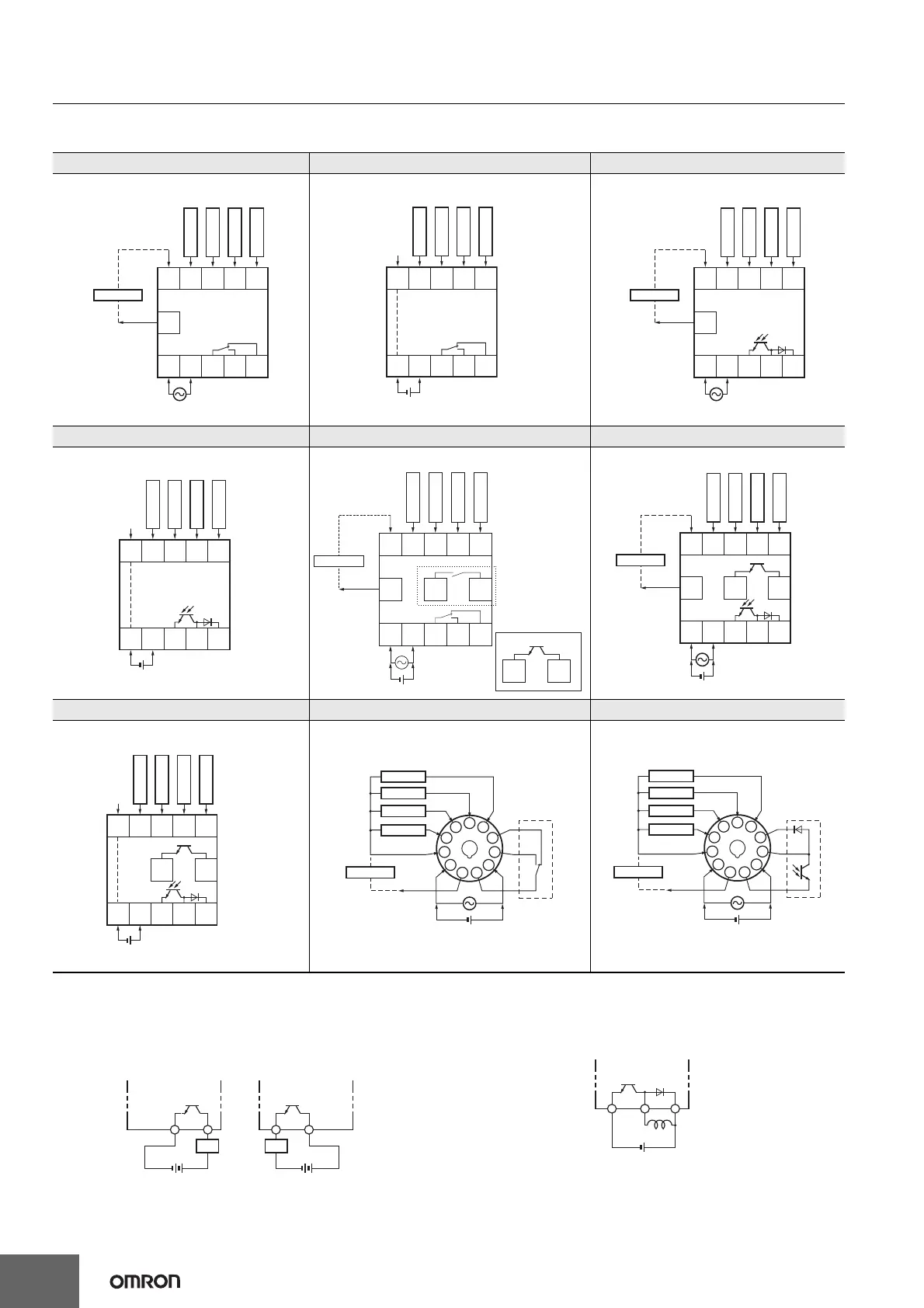
Connections
Terminal Arrangement
Confirm that the power supply meets specifications before use.
Transistor Output
• The transistor output of the H7CX is isolated from the internal
circuitry by a photocoupler, so the transistor output can be used as
both NPN and PNP output.
• The diode connected to the collector of the output transistor is used
to absorb inverted voltage that is generated when an inductive load
is connected to the H7CX.
H7CX-A-N/-A4-N H7CX-AD-N/-A4D-N H7CX-AS-N/-A4S-N
1-stage Contact Output 1-stage Contact Output
Terminals 1 and 6 are connected internally.
1-stage Transistor Output
H7CX-ASD-N/-A4SD-N H7CX-AW-N/-A4W-N/-AWD1-N/-AU-N/-AUD1-N H7CX-AWS-N/-AWSD1-N/-AUSD1-N
1-stage Transistor Output
Terminals 1 and 6 are connected internally.
2-stage Contact Output 2-stage Transistor Output
H7CX-AWSD-N/-A4WSD-N H7CX-A11-N/-A114-N/-A11D1-N/-A114D1-N H7CX-A11S-N/-A114S-N/-A11SD1-N
2-stage Transistor Output
Terminals 1 and 6 are connected internally.
1-stage Contact Output 1-stage Transistor Output
678910
11
OUT
(−)
(+)
0 V
12345
Reset
Total reset
CP2
CP1
Sensor
12 VDC
External
power supply
678910
OUT
(+)
(−)
0 V
12345
Reset
Total reset
CP2
CP1
678910
11
12345
OUT
0 V
(−)
(+)
Reset
Total reset
CP2
CP1
Sensor
12 VDC
External
power supply
678910
0 V
12345
OUT
(+)(−)
Reset
CP2
CP1
Total reset
678910
11 12 13
OUT1
12345
OUT2
(+)(−)
0 V
(−)
(+)
Reset 1
CP2
CP1
12 VDC
External
power supply
Reset 2
Sensor
12 13
*
1
1: “-AU@” Models
*
*
678910
11 12 13
12345
OUT1
OUT2
0 V
(+)(−)
(−)
(+)
Reset 1
CP2
CP1
Sensor
12 VDC
External
power supply
Reset 2
678910
12 13
0 V
12345
OUT1
OUT2
(+)(−)
Reset 1
CP2
CP1
Reset 2
6
7
8
9
10
11
1
2
3
4
5
(+)(−)
OUT
0 V
(−)
(+)
Reset
Total reset
CP2
CP1
Sensor
12 VDC
External
power supply
Internal circui

 Loading...


