1-5
1-4 System Block Diagrams
1
OMNUC G5-SERIES AC SERVOMOTOR AND SERVO DRIVE USER'S MANUAL
Features and System Configuration
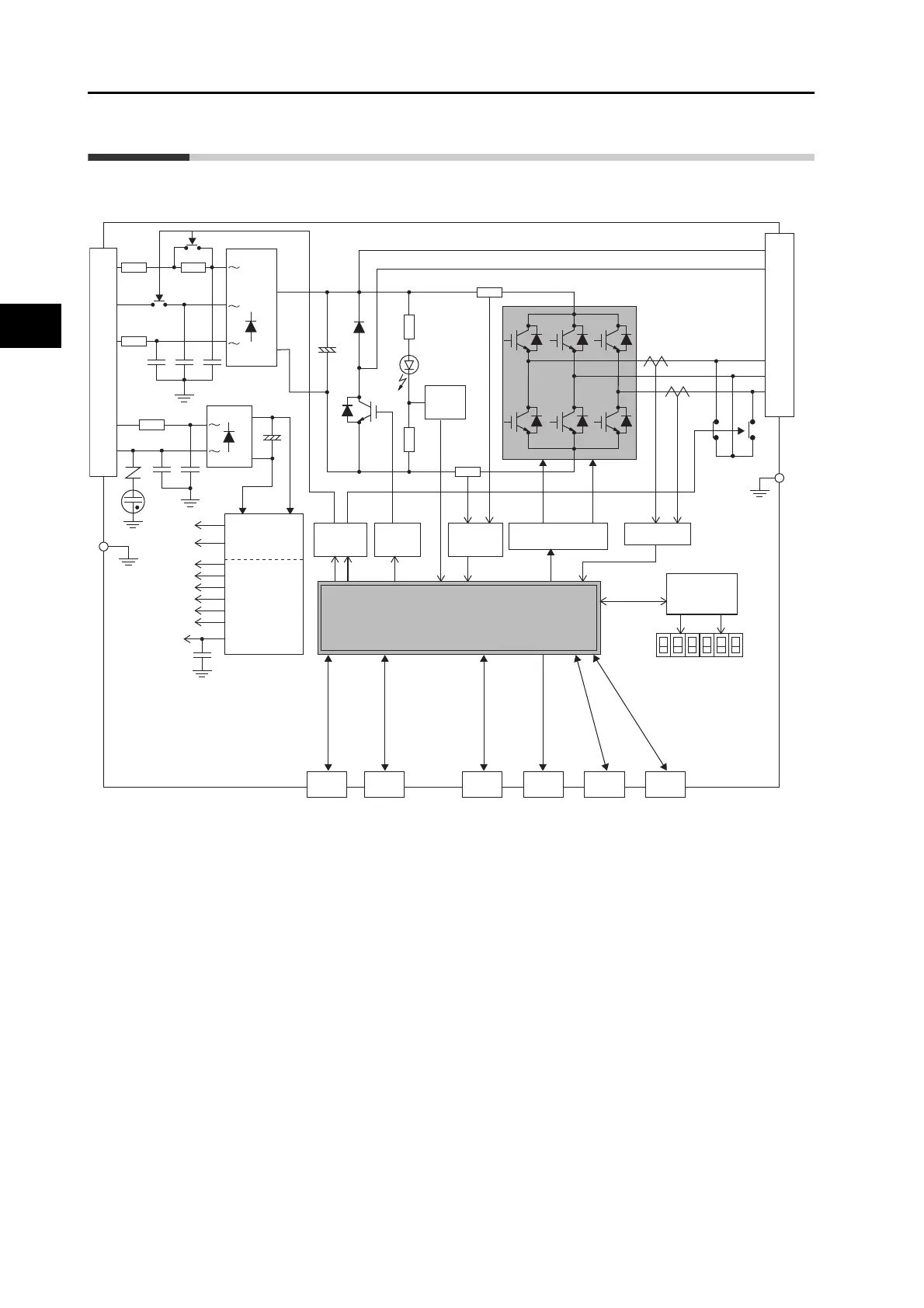
1-4 System Block Diagrams
R88D-KTA5L/-KT01L/-KT02L/-KT01H/-KT02H/-KT04H
CN2 CN4 CN5 CN7 CN8CN1
Display and
setting circuit
area
Gate drive
SW power
supply main
circuit control
Internal
control power
supply
FG
L2C
L1C
L3
L2
L1
FUSE
FUSE
FUSE
CN A
+
-
+
-
15 V
G1
5 V
2.5 V
1.5 V
±12 V
E5 V
G2
3.3 V
Overcurrent
detection
Current detection
Voltage
detection
Regeneration
control
Relay
drive
FG
Control
interface
B1
B2
B3
CN B
U
V
W
MPU & ASIC
Position, speed, and torque calculation control area
• PWM control
Encoder
External
encoder
Analog
monitor
USB
Safety
 Loading...
