Varispeed V7
217
Frequency Inverters
Main Circuit
Control Circuit
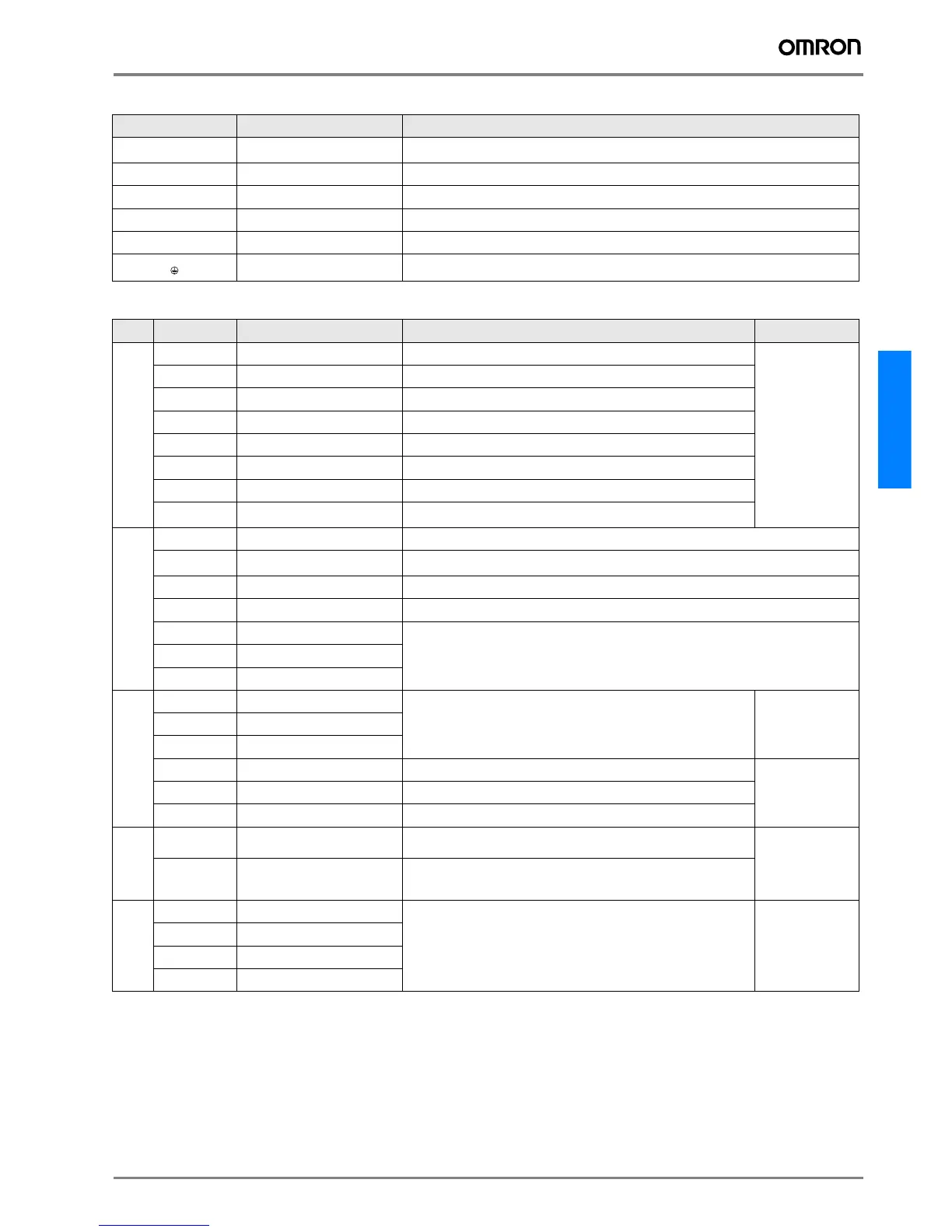
Terminal Name Function (Signal Level)
R/L1, S/L2, T/L3
AC Power Supply Input
Main circuit power supply input (Use R/L1 and S/L2 for single-phase power supply inverter. Do not
use T/L3 of the models less than 0.75kW for other usage, such as a junction terminal.)
U/T1, V/T2, W/T3
Inverter Output For inverter output
B1, B2
Braking Resistor Connection For braking resistor connection
+2, +1
DC Reactor Connection
Remove the short bar between +2 and +1 when connecting DC reactor (option)
+1, –
DC Power Supply Input
For power supply input (+1: positive electrode; – : negative electrode)*
Grounding For grounding (Grounding should be conforming to the local grounding code.)
Type No.
Signal Name Function Signal Level
Digital input signals
S1
Multi-function Input Selection 1 Factory setting: Runs when CLOSED, stops when OPEN.
24VDC, 8mA
photocoupler
insulation
S2
Multi-function Input Selection 2 Factory setting: Runs when CLOSED, stops when OPEN.
S3
Multi-function Input Selection 3 Factory setting: "Fault reset"
S4
Multi-function Input Selection 4 Factory setting: "External fault (NO contact)"
S5
Multi-function Input Selection 5 Factory setting: "Multi-step speed reference 1"
S6
Multi-function Input Selection 6 Factory setting: "Multi-step speed reference 2"
S7
Multi-function Input Selection 7 Factory setting: "JOG command"
SC
Multi-function Input Selection
Common
Common for control signal
Analog input
signals
RP
Speed Reference Pulse Train Input 33kHz max.
FS
Power Supply Terminal for
Frequency Setting
+12V (allowable current: 20mA max.)
FR
Speed Frequency Reference 0 to +10V DC (20kΩ) or 4 to 20mA (250Ω), 0 to 20 mA (250Ω) (resolution 1/1000)
FC
Frequency Reference Common 0V
1 (CN2)
Multi-function analog voltage input
Voltage input (between terminals 1 and 3): 0 to 10 V DC ( Input impedance: 20 kΩ)
Current input (between terminals 2 and 3): 4 to 20 mA (Input impedance: 250 Ω)
2 (CN2)
Multi-function analog current input
3 (CN2
Multi-function analog input common
Digital output signals
MA
NO Contact Output
Factory setting: "Fault"
Contact capacity
250V AC,
1A or less
30VDC, 1A
or less
NC
Contact Output
MC
Contact Output Common
P1
Photocoupler Output 1 Factory setting: "Running"
Photocoupler output:
+48VDC, 50mA or
less
P2
Photocoupler Output 2 Factory setting: "At frequency"
PC
Photocoupler Output Common 0V
Analog output
signals
AM
Analog Monitor Output
Factory setting: "Output frequency" 0 to +10V output
(Pulse monitor output available by setting constants. Duty: 30 to 70%)
0 to 10V 2mA
or less
Resolution: 8bits
AC
Analog Monitor Common 0V
RS-485/422
R+
Communication Input (+)
For MEMOBUS communication
Operation by RS-485 or RS-422 communication is available.
RS-485/422
MEMOBUS
protocol
19.2kBPS max.
R–
Communication Input (–)
S+
Communication Output (+)
S–
Communication Output (–)
 Loading...


