ADJUSTMENTS
ANTI-FLICKER CONDENSER
AND CONNECTIONS USED PRIOR
TO
SPEC.
C
POINTS SPRING MUST
JHESE
SCREWS MUST
BE
NOT
RUB
WIRE LOOSENED
TO ADJ UST
POSITION
OF
BREAKER
'
BOX
MOVE
BOX
UP
TO RETARD
.SPjARK
— MOVE
BOX
DOWN
TO ADVANCE
SPARK
LEADS GROUNDING
AGAINST
CO VER
WILL
CAUSE IGNITION FAILURE
PRY LEADS
OFF
WITH SCREW
DRIVER
TO RE-
MOVE THEM
ISANTI-FLICKER BREAKER
OINTS
IGNITION BREAKER
POINTS
SET GAP AT 0.020"
PLACE
A
DROP
OF
LIGHT
OIL ON
BREAK-
ER
ARM
PIVOT SHAFT
EVERY TIME POINTS
;
ARE CHANGED.
LOOSEN
THE
SCREWS
TO ADJUST POSITION
OF
BREAKF.R
BOX
SET BREAKER POINT-
GAP WIDTH
AT
0.020"
A958 TERMINAL
VACU-FLO COOLED MODELS HAVING
FLYWHEEL WITH FOUR TIMING MARKS-
USE THIS MARK.
(PAINTED WHITE
ON
LATER MODELS)
TC
TIMING
FLYWHEEL
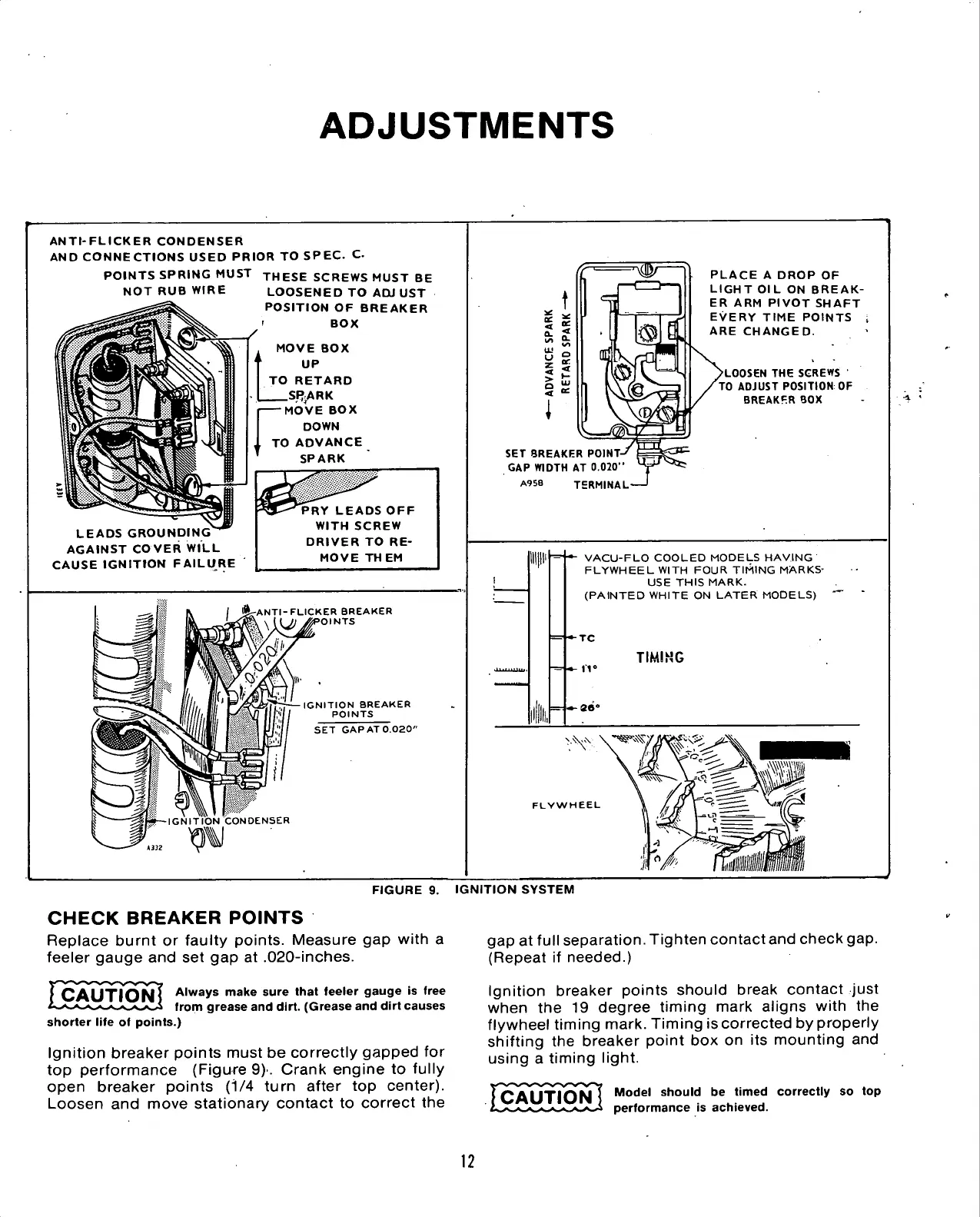
FIGURE
9.
IGNITION SYSTEM
CHECK
BREAKER
POINTS
Replace burnt
or
faulty points. Measure
gap
with
a
feeler gauge
and set gap at
.020-inches.
|Q^yy|Q(iJ7 Always make sure that feeler gauge
is
free
i^x-x^^^^-^^i
from
gre
i grease
and
dirt. (Grease
and
dirt causes
shorter life
of
points.)
Ignition breaker points must
be
correctly gapped
for
top performance (Figure
9)'.
Crank engine
to
fully
open breaker points
(i/4
turn after
top
center).
Loosen
and
move stationary contact
to
correct
the
gap
at
full separation. Tighten contact and check
gap.
(Repeat
if
needed.)
Ignition breaker points should break contact just
when
the 19
degree timing mark aligns with
the
flywheel timing mark. Timing
is
corrected
by
properly
shifting
the
breaker point
box on its
mounting
and
using
a
timing light.
^Q^yyjoj^l^
Model should
be
timed correctly
so top
performance
is
achieved.
12
 Loading...

