5
TYPICAL GENSET
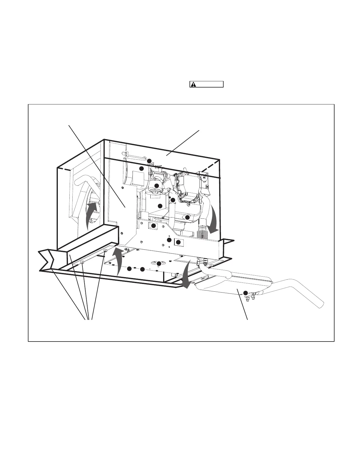
Figure 1 illustrates a typical genset installation. For
clarity, the genset compartment door and front pan-
els (provided by the vehicle manufacturer) are not
shown. See OUTLINE DRAWING (Page A-1) for
installation details: mounting bolt hole locations,
connection points (fuel, battery, remote control, AC
output and exhaust), sizes and types of fittings, inlet
and outlet air openings, weight and overall dimen-
sions, etc. See your Onan dealer for large-scale
copies of the drawings.
CAUTION
Do not tip the genset forward or oil
will spill into the breather.
COOLING
AIR
HOT AIR
DISCHARGE
MUFFLER/TAILPIPE
ASSEMBLY
STEEL ENCLOSURE AND COOLING AIR PLENUM THAT SEALS TIGHT
AROUND SIDES, TOP AND FRONT TO PREVENT AIR RECIRCULATION. FRONT
ACCESS COVER MUST ALSO SEAL TIGHT (COACH MANUFACTURER)
AIR SEAL
PANEL
THE DOTS REPRESENT
LOCATIONS REQUIRING
ACCESS FOR OPERATION AND
PERIODIC MAINTENANCE
VEHICLE FRAME, GENSET OUTRIGGERS
AND 2 OF 4 MOUNTING BOLTS
FIGURE 1. TYPICAL GENSET INSTALLATION
Redistribution or publication of this document,
by any means, is strictly prohibited.
 Loading...
