Do you have a question about the Onkyo HT-R391B and is the answer not in the manual?
| Type | AV Receiver |
|---|---|
| Channels | 5.1 |
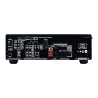
| HDMI Inputs | 4 |
| HDMI Outputs | 1 |
| Power Output | 100 W |
| 4K Passthrough | Yes |
| Bluetooth | Yes |
| AM/FM Tuner | Yes |
| Dolby Support | Dolby TrueHD, Dolby Digital Plus |
| DTS Support | DTS-HD Master Audio |
| Total Harmonic Distortion | 0.08% |
| Frequency Response | 10 Hz-100 kHz/+1 dB, -3 dB (Direct Mode) |
| Input Sensitivity and Impedance | 200 mV/47 kΩ (Line) |
| Dimensions (W x H x D) | 435 x 160 x 328 mm |
| Power Output per Channel | 100W (6 ohms, 1 kHz, 1% THD) |
Instructions for replacing fuses and safety precautions.
Post-repair safety checks for US models, focusing on leakage current.
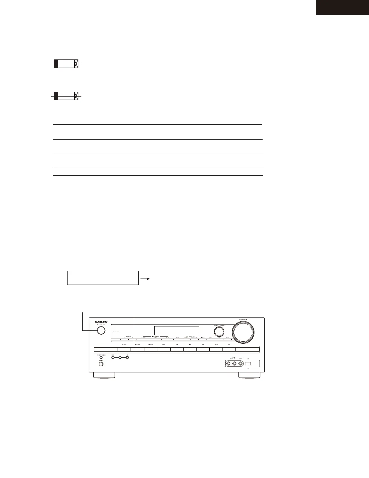
Steps to display and check firmware versions of the unit's processors.
Description of DSP port states and their inferred meanings.
Explanation of DSP sequence codes and potential causes/solutions.
Further details on DSP sequence codes and their meanings.
How input resolutions are displayed in HDMI debug mode.
How output resolutions are displayed in HDMI debug mode.
Displays input resolution for 4K upscaling mode.
Displays output resolution for 4K upscaling mode.
Detailed display of resolution information including 3D format.
Displays various 3D format settings and options.
Displays PC resolution information.
General operation checks and procedures.
Further operation checks and procedures.
Introduction to test modes and FL display.
Detailed list of test modes for operations.
Detailed list of auto measurement modes.
Lists test modes for video and HDMI.
Instructions for updating firmware via USB.
Detailed steps for performing the USB firmware update.