ADJUSTMENT PROCEDURE-1
IDLING CURRENT ADJUSTMENT
HT-R640
[Procedure]
<Note> No load and No signal
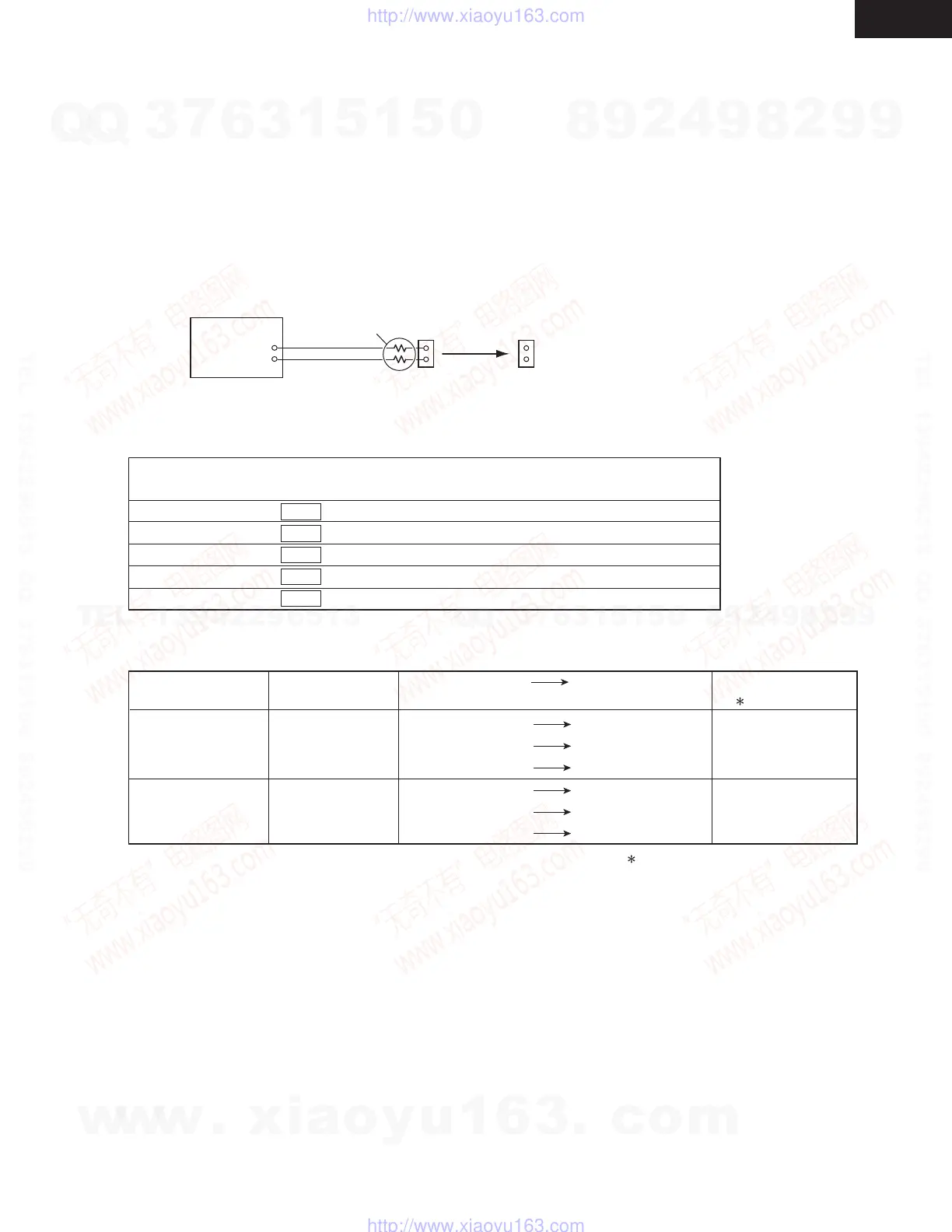
Refer to <Fig-1> in " ADJUSTMENT PROCEDURES-2 " for the adjustment points and the test points.
1. Before idling adjustment, turn the trimming resistors to counter clockwise.
2. Connect the dc voltmeter to test points,
using two 100 ohm resistors between the poles of the jig terminal and the dc voltmeter terminals.
6. Wait for 4 - 6 minutes. (Heat running)
7. Re-adjust the trimming resistors as the following procedure.
Adjustment point
(Trimming resistor)
R6040
R6041
R6042
R6043
R6044
Adjustment value
2.5 mV
2.5 mV
2.5 mV
1.5 mV
1.5 mV
Measuring point
(Test point)
P6080
P6081
P6082
P6083
P6084
Adjustment point
R6041, R6042
and R6040
R6043, R6044
Adjustment value
9 mV
Leave it as it is
11 mV
6 mV
Leave it as it is
8 mV
Measured value
In case below 9 mV
In case 9 - 11 mV
In case over 11 mV
In case below 6 mV
In case 6 - 8 mV
In case over 8 mV
3. Connect the ac power cord to wall outlet.
4. Press the STANDBY/ON button to turn the power on.
5. Adjust the trimming resistors as the following procedure immediately after power on.
Channel
Center
Front Left
Front Right
Surround Left
Surround Right
Channel
Front Left, Right
and Center
Surround Left
Surround Right
ID+
ID-
Test point
DC voltmeter
Jig terminal
100 ohms
1/4watts
8. Disconnect the dc voltmeter.
9. Press the STANDBY/ON button to turn the power off.
10. Disconnect the ac power cord.
Specifications
( In a stable state)
12 +/- 3 mV
9 +/- 3 mV
Idling currents are stabilized in about
10 minutes after power on.
[When]
Exchange Power transistor (Q6050 - Q6054, Q6060 - Q6064) and Amplifier PC board (NAAF-8911).
Mark
C
L
R
SL
SR
w
w
w
.
x
i
a
o
y
u
1
6
3
.
c
o
m
Q
Q
3
7
6
3
1
5
1
5
0
9
9
2
8
9
4
2
9
8
T
E
L
1
3
9
4
2
2
9
6
5
1
3
9
9
2
8
9
4
2
9
8
0
5
1
5
1
3
6
7
3
Q
Q
TEL 13942296513 QQ 376315150 892498299
TEL 13942296513 QQ 376315150 892498299
http://www.xiaoyu163.com
http://www.xiaoyu163.com
 Loading...