No.
Function
I/O Act Description
1
OSDDA O H Serial data signal output pin to OSD IC.
2
OSDCL O CLK Serial clock signal output pin to OSD IC.
3
OSDCS O H Chip select signal output pin to OSD IC.
4
SVS1 O H Logic output pin of S video 1.
5
SVS2 O H Logic output pin of S video 2.
6
VCC Power supply pin. Connect to 5V.
7
VSS Power supply pin. Connect to the ground.
8
SVS3 O H Logic output pin of S video 3..
9
SVS4 O H Logic output pin of S video 4.
10
SVS5 O H Logic output pin of S video 5.
11
SVS6 O H Logic output pin of S video 6.
12
VCS1 O H Logic output pin of video 1.
13
VCS2 O H Logic output pin of video 2.
14
VCS3 O H Logic output pin of video 3.
15
VCS4 I/O H Logic output pin of video 4.
16
VCS5 O H Logic output pin of video 5.
17
VCS6 O H Logic output pin of video 6.
19
POWER O H Output pin to control the power supply of amplifier section.
20
PUREPOWER
O H Not used.
21
Z2LMUT O H Not used.
22
Z2MUT O H Muting control output pin for Zone 2.
23
AMUT O H Audio muting control output pin.
24
PLLSTB O H Strobe signal output pin to PLL IC in the tuner pack.
25
PLLSDO O H Data signal output pin to PLL IC.
26
PLLCLK O H Clock signal output pin to PLL IC.
27
TMUT O H Muting control output pin for tuner section.
28
FSTB O H Not used.
29
FCL O H Not used.
30
FDA O H Not used.
31
~RESET System reset pin
35
XOUT Oscillator circuit output pin for main clock. Connector the 16MHz ceramic resonator.
36
XIN Oscillator circuit input pin for main clock. Connector the 16MHz ceramic resonator.
37
VSS Power supply pin. Connect to the ground.
38
VCC Power supply pin. Connect to 5V.
41
CNPT O H Composite signal selector pin.
42
T12VB O H Not used.
43
T12VA O H Not used.
44
SELMUT O H Muting control signal output pin to BD3811.
45
SELCLK O H Clock signal output pin to BD3811.
46
SELSDO O H Data signal output pin to BD3811.
47
DIRINT1 I H Interrupter signal input pin from DIR IC.
48
DIRINT0 I H Interrupter signal input pin from DIR IC.
49
~DIRCS O L Chip select signal output pin to DIR IC.
50
~DIRPD O L Power down signal output pin to DIR IC.
51
~DSPRST O H Reset signal output pinto DIR IC.
52
~INTREQ I L Interrupter signal of DSP IC and rollback signal input/output pin.
53
DSPSDI I H Serial data signal input pin from DIR and DSP ICs.
54
~DSPCS O L Chip select signal output pin to DSP IC.
55
BVDD Power supply pin. Connect to 3.3V.
56
BVSS Power supply pin. Connect to ground.
57
DSPCLK O H Serial clock signal output pin to DIR and DSP ICs.
58
DSPSDO O H Serial data signal output pin to DIR and DSP ICs.
59
~ROM/RAM O L/H ROM/RAM select pin to DSP IC.
94
SUBSDI/SI
IH
Data signal input pin from the sub microprocessor.
95
SUBSDO/SO
OH
data signal output pin to the sub microprocessor.
96
SUBCLK/SCL
OCLK
Clock signal output pin to the sub microprocessor.
97
232RXD
IH
Not used.
98
232TXD
OH
Not used.
99
SUBRST/HS
OH
Reset signal output pin to the sub microprocessor.
100
PROTECT
IH
over current and over voltage detection input pin.
60
A15 O H Address 15 output pin to Boot ROM.
61
A16 O H Address 16 output pin to Boot ROM.
62
A17 O H Address 17 output pin to Boot ROM.
63
A18 O H Address 18 output pin to Boot ROM.
65
SPF O H Speaker relay control signal output pin for the front channel.
66
SPCS O H Speaker relay control signal output pin for the center and surround channels.
67
SPB O H Speaker relay control signal output pin for the speaker B.
68
VPPEN O H Vpp voltage generation circuit to rewrite the program.
70
HPMUT O H Muting control signal output pin for headphone.
71
VCC Power supply pin. Connect to 5V.
72
VSS Power supply pin. Connect to the ground.
73
VCC Power supply pin. Connect to 5V.
74
VOLH I ANA Output level detection input pin.
75
MODEL I ANA Initializing input pin of model.
76
STEREO I H Stereo broadcast detection input pin.
77
~SD I L Broadcast detection input pin more than the muting level.
78
RDSEN I H Initializing input pin of RDS broadcast.
79
PALEN I L/H Initializing input pin of PAL or NTSC.
80
AREA1 I H Initializing input pin of band aria.
81
AREA2 I H Initializing input pin of band aria.
83
SDET I H S video signal detection input pin
84
RDSDA I H Data input pin from RDS decoder.
85
RDSSIG I H Signal input pin from RDS decoder
86
SYNC I H External synchronizing judgement input pin from OSD IC.
87
~VSYNC I L Vertical synchronizing signal input pin.
88
~POFF I L Power failure detection input pin.
89
RDSSCK I CLK Clock signal input pin from RDS decoder.
90
~IRIN I L Not used.
91
~IRZ2 I L Not used.
92
SEC1H O H Amplifier gain control output pin.
93
SUBRDY I H Ready signal input pin from the sub microprocessor.
No. Function I/O Act Description
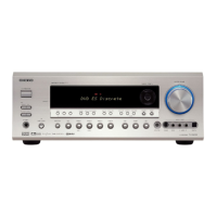
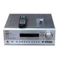
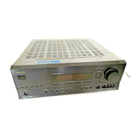
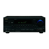
TX-SR600/E
MAIN MICROPROCESSOR-TERMINAL DESCRIPTIONS
TX-SR600E
 Loading...