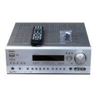
TX-SR674/674E/8467
MICROPROCESSOR TERMINAL DESCRIPTIONS
No. Pin Name Function I/O Act. Description
65 P47/~CS3 AMUT O H
66 P46/~CS2 SPRLZ2 O H
67 P45/~CS1 O H
Audio mute control pin
68 P44/~CS0
SPRLF
OH
Front speaker relay control pin
69 P43/A19
SPRLCS
OH
Center/Surround Back speaker relay control pin
70 P42/A18
SPRLSB
OH
Surround Back speaker relay control pin
71 P41/A17 VOLDATA O H
ZONE speaker relay control pin
72 P40/A16 VOLCLK O
H
73 P37/A15 O H
74 P36/A14 O
ELK
75 P35/A13
I
H
76 P34/A12 ~POFF2
O
L
77 P33/A11 ~FANH O L
78 P32/A10
VPOWER
OL
Power control output to video section
79 P31/A09
APOWER
OH
Power source control output
80 P124 O H
81 P123
~FANCTRL
O
H
82 P122 O H
83 P121 O H
84 P120 O H
ZONE 12V trigger output
85 VCC2 Vcc2
Power supply
86 P30/A8(/-/D7) SEC1H O H
Voltage-select control pin
87 VSS Vss
Power supply Ground
88 P27/AN27/A7(/D7/D6) PROTECT I H
Signal level protection detect pin
89 P26/AN26/A6(/D6/D5) VOLH I A/D
Thermal protection detect pin
90 P25/AN25/A5(/D5/D4) THERMAL I
Protection detect pin
91 P24/AN24/A4(/D4/D3) INIT3
92 P23/AN23/A3(/D3/D2)
93 P22/AN22/A2(/D2/D1)
94 P21/AN21/A1(/D1/D0) BAND I
95 P20/AN20/A0(/D0/-) ~SYSOUT
I
H
96 P17/D15/~INT5 SYSIN I H
RI input pin
97 P16/D14/~INT4 ~IRIN I L
IRIN remote control input pin
98 P15/D13/~INT3 ~REMIN I L
99 P14/D12 ~STEREO
O
L
RI output pin
100 P13/D11 ~SD
H
101 P12/D10
102 P11/D9
H
STANDBY LED control pin
103 P10/D8
H
104 P07/AN07/D7
MICMUT
H
Headphone detection input
105 P06/AN06/D6
~MICDET
Microphone detection input
106 P05/AN05/D5
VOLB
Master volume rotary encoder input
107 P04/AN04/D4
VOLA
108 P03/AN03/D3
Initializing pin 3
109 P02/AN02/D2
Initializing pin 2
110 P01/AN01/D1
Initializing pin 1
111 P00/AN00/D0
Initializing pin for tuner frequency
112 P117
LEDZONE2
O
H
Zone LED control pin
113 P116
114 P115
115 P114
116 P113 O
H
Serial data output for FL driver
117 P112
H
Serial clock output for FL driver
118 P111 O
H
Chip select output for FL driver
119 P110
H
Reset output for FL driver
120 P107/AN7/~KI3 ~KEYINT3 I L
Key input interrupt 3
121 P106/AN6/~KI2 ~KEYINT2 I L
Key input interrupt 2
122 P105/AN5/~KI1 ~KEYINT1 I L
Key input interrupt 1
123 P104/AN4/~KI0 ~KEYINT0 I L
Key input interrupt 0
124 P103/AN3 KEY I A/D
Key input 3
125 P102/AN2 KEY I A/D
Key input 2
126 P101/AN1 KEY I A/D
Key input 1
127 AVIS AVss
Ground for A/D
128 P100/AN0 KEY I A/D
Key input 0
ELK
I
I
I
I
I
I
I
O
O
O
O
O
O
O
I
O
O
O
I
I
INIT2
INIT1
HPDET
LEDSTBY
FLDSDO
FLDCLK
~FLDCS
~FLDRST
~VMRST
VMSTB
TXMUTE
RXMUTE
A/D
A/D
A/D
A/D
A/D
H
H
H
L
L
L
L
H
H
H
TRGZ2
TRGB
TRGA
Z2VOLMUT
Z2VOLCLK
Z2VOLDAT
No use
No use
No use
No use
No use
No use
No use
No use
No use
No use
No use
No use
No use
Data output to R2S15211
Clock output to R2S15211
POFF detect pin
Remote controller signal input pin
FM Stereo detect pin
FM/AM TUNED detect pin
Microphone mute output
HDMI microprocessor reset pin
HDMI microprocessor strobe input
HDMI microprocessor mute pin
HDMI microprocessor RXMUTE detect pin
Master volume rotary encoder input
Q701: M30627FHPGP
 Loading...