Select "N.O."/"N.C." for safety output.
The delay time between test input and
safety output is 10 ms.
Set this switch to snow if the sensor is used in
a region with snow or a lot of insects.
Test input
(
from door controller
)
High
13
Low
13
65
Setting 1
65
Setting 2
65
Setting 3
65
Setting 4
2.0 to 3.0 m
21
Low
2.0 to 3.0 m
21
Middle
2.5 to 3.2 m
21
High
3.0 to 3.5 m
21
S-High
43
30 sec
43
60 sec
43
180 sec
43
600 sec
Select "N.O."/"N.C." for activation output.
Activation output
(to door controller)
Rain mode
Normal
7
Rain
7
Normal
8
Snow
8
Safety output
(to door controller)
N.O.
11
N.C.
11
OFF
10
ON
10
N.O.
12
N.C.
12
Bi
9
Uni
9
Snow mode
Direction
Immunity
Set this switch to rain if the sensor is used in
a region with a lot of rain.
When dipswitch 9 is set to "Uni", this setting
enables the door to close faster when a
person walks away from the door.
Set dipswitch 10 to "ON" when the sensor
operates by itself (Ghosting).
When dipswitch 10 is set to "ON" the actual
detection area may occur smaller.
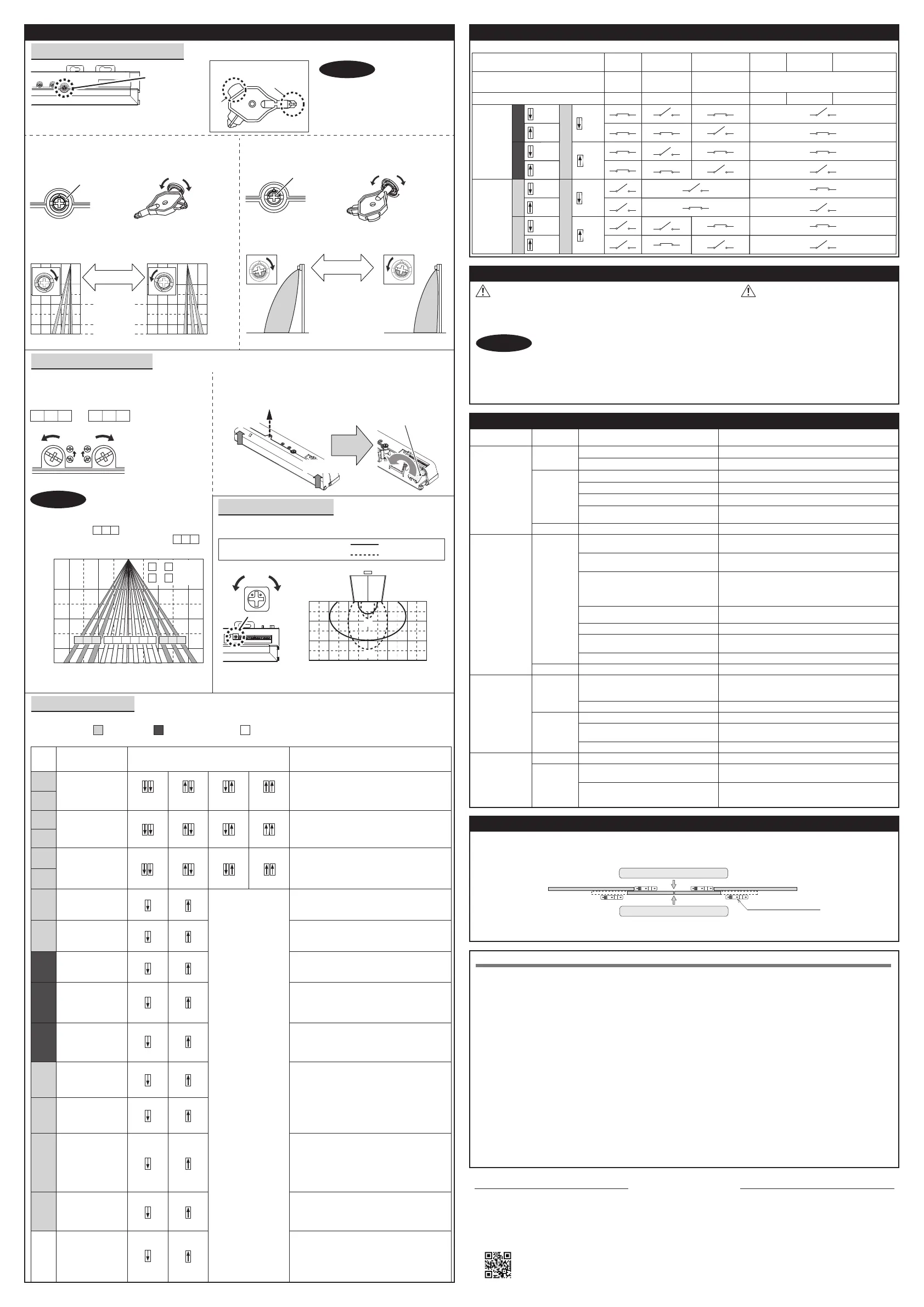
Adjustments
When adjusting the 2nd row close to the door,
see Table 2 dipswitch 16 for the easier adjustment.
Make sure that the detection area
does not overlap with the door/header,
and there is no highly reflecting object
near the detection area otherwise
ghosting/signal saturation may occur.
Depth angle
adjustment
screw
Area adjustment tool
A
B
1. Area depth angle adjustment
NOTE
a. AIR adjustment b. Microwave adjustment
Depth angle adjustment screw for the AIR area. Depth angle adjustment screw for the microwave area.
Use the area adjustment tool (A) as shown above to
change the area depth angle.
For the easier adjustment, see Reference.
Use the area adjustment tool (B) as shown above to change
the area depth angle.
Shallow
Deep
Red
Shallow Deep
Blue
ShallowDeep
ShallowDeep
[feet,inch(m)]
3′3"
(1.0)
3′3"
(1.0)
0
-3′3"
(-1.0)
0
6′7" (2.0)
9′10" (3.0)
11′6" (3.5)
To adjust the AIR detection area width, use the
adjustment screws as shown in the picture below.
Width adjustment screws
Narrow
Wide
Eliminated
Eliminated
1 2 3
10 11 12
Please adjust
by using the tool (B).
a. AIR adjustment
2. Area width adjustment
Front view
[feet,inch(m)]
4 9
1 12
~
~
:Wide
:Narrow
1 2 3
10 11 12
4 5 6 7 8 9
6′7"
(2.0)
0
9′10"
(3.0)
11′6"
(3.5)
0
6′7"
(2.0)
6′7"
(2.0)
3′3"
(1.0)
3′3"
(1.0)
NOTE
When setting the detection area
width, make sure to turn the
adjustment screws until it clicks.
cannot be eliminated
separately, neither can .
1 2 3
10 1112
Table 2
4. Dipswitch settings
AIR settings
Microwave settings
Other setting
Comment
Set the sensitivity according to the mounting
height. Values below dipswitches are
reference only. Adjust the sensitivity
according to your risk assessment.
Setting
1
Function
Sensitivity
No.
2
To enable the presence detection, do not
enter the detection area for 10 s after setting
the timer.
Presence timer
3
4
When using more than one sensor close to
each other, set the frequency different for
each sensor.
Frequency
5
6
To adjust the microwave detection area width, use the narrow lens
as shown in the picture below.
b. Microwave adjustment
Adjust the microwave detection area with potentiometer.
3. Microwave sensitivity
H
L
Top view
H
L
[feet,inch(m)]
3′3"
(1.0)
6′7"
(2.0)
9′10"
(3.0)
0
9′10"
(3.0)
6′7"
(2.0)
3′3"
(1.0)
09′10"
(3.0)
6′7"
(2.0)
3′3"
(1.0)
Low High
Mounting height : 7'3" (2.2 m)
Vertical adjustment : +35°
Wide area
Narrow area
Narrow lens1. Remove screw
2. Open
2. Open
7
8
9
10
13
12
Simultaneous
output
BLUEZONE
(1st row)
OFF
15
ON
15
OFF
14
ON
14
When dipswitch 14 is set to "ON", both the
activation & safety relay outputs will operate
simultaneously regardless of detection area.
But only the safety output relay, will respond
back with a safety output when it receives a
test input.
When dipswitch 15 is set to "ON", the
BLUEZONE(1st row) is active and looks
through the threshold.
Installation mode
OFF
16
ON
16
Set dipswitch 16 to "ON" to adjust the 2nd
row. During the installation mode only the 2nd
row remains active and the operation indicator
shows Yellow. After setting the row set
dipswitch 16 "OFF".
14
15
16
11
Check the operation in the operation mode according to the chart below.
Checking
Entry
Outside of
detection area
Entry into
microwave area
Entry into
BLUEZONE(1st row)
Entry into
3rd row
Entry into
2nd row
Power
OFF
Activation
output
Safety
output
14
14
OFF
ON
OFF
ON
11
N.O.
N.C.
N.O.
N.C.
N.O.
N.C.
N.O.
N.C.
11
12
12
Status
Operation indicator
Stand-by
Green
Motion
detection
Orange
Motion/Presence
detection
Red Red blinking
Blue
-
None
1. Do not wash the sensor with water.
2. Do not disassemble, rebuild or repair the sensor yourself,
otherwise electric shock may occur.
1. Always keep the detection window clean. If dirty, wipe the window with a damp cloth. (Do not use any cleaner/solvent.)
2. When the operation indicator blinks Green, contact your installer or service engineer.
3. Always contact your installer or service engineer when changing the settings.
4. When turning the power ON, always walk-test the detection area to ensure the proper operation.
5. Do not place any objects that move or emit light in the detection area. (e.g. plant, illumination, etc.)
1. Do not paint the detection window.
Inform building owner/operator of the following items
WARNING
CAUTION
NOTE
Door operation
Operation
indicator
Possible cause Possible countermeasures
Troubleshooting
Door opens
when no one
is in the
detection area.
(Ghosting)
Unstable
Waterdrops on the detection window.
Use the rain-cover. (separately available)
Or wipe the detection window with a damp cloth.
Do not use any cleaner or solvent.
Or install in a place keeping the waterdrops off.
None
Wrong power supply voltage. Set to the stated voltage.
Wrong wiring or connection failure. Check the wires and connector.
Door does not
open when a
person enters
the detection
area.
Unstable
Wrong detection area positioning.
Check Adjustments 1, 2, 3.
Sensitivity is too low. Set the sensitivity higher.
Short presence timer. Set the presence timer longer.
Wrong wiring or settings. Check the wires and connector.Proper
Dirty detection window.
Wipe the detection window with a damp cloth.
Do not use any cleaner or solvent.
The detection area overlaps with that
of another sensor.
Check Table 2 dipswitch 5, 6.
Objects that move or emit light in the
detection area.
Remove the objects.
Adjust the detection area to "Deep"(outside).
Or set dipswitch 10 to "ON".
The detection area overlaps with the
door/header.
Sensitivity is too high. Set the sensitivity lower.
Set dipswitch "7","8","9","10" to "Rain","Snow",
"Uni","ON".
Raining or snowing.
Others Set dipswitch 10 to "ON".
Wrong setting of dipswitches.
Check Table 2 dipswitch 7, 8, 11.
Proper
Sudden change in the detection area.
Check Table 2 dipswitch 1 to 4. If the problem
still persists, hard-reset the sensor.
(Turn the power OFF and ON again)
Proper
Door remains
open.
Wrong wiring or connection failure. Check the wires and connector.
Fast
Green
blinking
Sensitivity is too low. Set the sensitivity higher.
Dirty detection window.
Wipe the detection window with a damp cloth.
Do not use any cleaner or solvent.
Contact your installer or service engineer.Sensitivity too low or sensor failure.
Installation mode is set to "ON". Set dipswitch 16 to "OFF".Yellow
Proper
operation.
Slow
Green
blinking
Adjust the detection area to "Deep"(outside).
Or set dipswitch 10 to "ON".
The detection area overlaps with the
door/header.
Signal saturation.
Remove highly reflecting objects from the
detection area. Or lower the sensitivity.
Or change the area depth angle for AIR area.
INFRARED FINDER
Detection area
Detection area
1. Turn the depth angle adjustment screw to the right (Deep) to place the detection area most away from the door.
2. Set INFRARED FINDER sensitivity to "H" (High) and place it on the floor as shown below.
Area depth adjustment with INFRARED FINDER (Separately available)
3. Turn the depth angle adjustment screw to the left (Shallow) until the emitting area is placed at the position where
INFRARED FINDER is in the low detection status (Slow Red blinking).
Reference
This device complies with part 15 of FCC Rules and Innovation, Science and Economic Development Canada’s licence-exempt RSS(s). Operation is subject to
the following two conditions: (1) this device may not cause harmful interference, and (2) this device must accept any interference received, including interference
that may cause undesired operation.
Le présent appareil est conforme à la partie 15 des règles de la FCC et aux normes des CNR d’Innovation, Sciences et Développement économique Canada
applicables aux appareils radio exempts de licence. L'exploitation est autorisée aux deux conditions suivantes: (1) l'appareil ne doit pas produire de brouillage,
et (2) l'appareil doit accepter tout brouillage subi, même si le brouillage est susceptible d'en compromettre le fonctionnement.
Note: This equipment has been tested and found to comply with the limits for a Class B digital device, pursuant to part 15 of the FCC Rules. These limits are
designed to provide reasonable protection against harmful interference in a residential installation. This equipment generates, uses and can radiate radio frequency
energy and, if not installed and used in accordance with the instructions, may cause harmful interference to radio communications. However, there is no guarantee
that interference will not occur in a particular installation. If this equipment does cause harmful interference to radio or television reception, which can be determined
by turning the equipment off and on, the user is encouraged to try to correct the interference by one or more of the following measures:
-Reorient or relocate the receiving antenna.
-Increase the separation between the equipment and receiver.
-Connect the equipment into an outlet on a circuit different from that to which the receiver is connected.
-Consult the dealer or an experienced radio/TV technician for help.
Changes or modifications not expressly approved by the party responsible for compliance could void the user's authority to operate the equipment.
FCC CAUTION
This transmitter must not be co-located or operated in conjunction with any other antenna or transmitter.
FCC NOTICE
This equipment complies with FCC/ISED radiation exposure limits set forth for an uncontrolled environment and meets the FCC radio frequency (RF) Exposure
Guidelines and RSS-102 of the ISED radio frequency (RF) Exposure rules as this equipment has very low levels of RF energy.
Cet équipement est conforme aux limites d’exposition aux rayonnements énoncées pour un environnement non contrôlé et respecte les règles les radioélectriques (RF)
de la FCC lignes directrices d'exposition et d’exposition aux fréquences radioélectriques (RF) CNR-102 de l’ ISDE puisque cet appareil a une niveau tres bas d'energie RF.
FCC/ISED Radiation Exposure Statement
FCC and ISED Statement
Contact
5-8-12, Ogoto, Otsu, Shiga, 520-0101 Japan
OPTEX CO., LTD.
Manufacturer
North and South America Subsidiary
OPTEX INCORPORATED
10741 Walker Rd. Suite 300 Cypress, CA 90630 U.S.A
www.optexamerica.com Tel : +1(800)877 6656
 Loading...