INSTALLATION INSTRUCTIONS
No.59-3425-0 2307-25
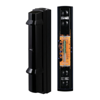
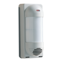
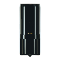
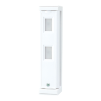
PHOTOELECTRIC DETECTOR
PHOTOELECTRIC DETECTOR
A photoelectric detector consists of an infrared light source that generates IR(Infrared)
beams, and an IR receiver that detects the IR beams.
The transmitter and receiver are installed on opposite sides of the area to be monitored.
The receiver detects when the IR beams are physically interrupted by an intruder,
and sends an alarm signal to a control panel.
Detection range
SL-200QN
SL-350QN
SL-650QN
Model
Transmitter Receiver
Smart Line series
Smart Line series
™
™
06 m/200 ft.
100 m/350 ft.
002 m/650 ft.
Visit the Web site to find various language
versions with full detailed instructions.
Receiver
Transmitter
(different
model)
Receiver
(different
model)
Transmitter
At least 1 m
Pole size
34 - 48 mm
[Receiver]
Transmitter
Receiver
1
Remove the cover.
2
1
2
Remove the main unit from the chassis.
Pull the upper part of
main unit, and raise it
to remove.
Turn the optical unit 90
degrees and loosen the
screws (both sides).
Caution
3
4
1
2
5
6
Pull
Loosen the
cover lock screw.
2
Twist it lightly.
1
3
A coin
(Not included)
<Transmitter>
(1) +
(2)
-
(3)
(7)
(8)
(9)
<Receiver>
POWER INPUT
10.5 - 30 V DC
POWER INPUT
10.5 - 30 V DC
SPARE
TAMPER OUTPUT (N.C.)
(1) +
(2)
-
(3)
(4) N.O.
(5) N.C.
(6) COM.
(7)
(8)
(9)
SPARE
ALARM OUTPUT
TAMPER OUTPUT (N.C.)
Unstable installation
Swing/block the beam Direct sunlight Crosstalk Appropriate height
Distance
Do not expose to direct sunlight that may damage
the optics during installation.
Preparation
Terminal
Features
- 1 -
This symbol indicates prohibition.
This symbol indicates recommendation.
Precautions
Warning
Caution
• Read this instruction manual carefully prior to installation.
• After reading, store this manual carefully in an easily accessible place for reference.
• This manual uses the following warning indications for correct use of the product, harm to
you or other people and damage to your assets, which are described below. Be sure to
understand the description before reading the rest of this manual.
Failure to follow the instructions provided with this indication and
improper handling may cause death or serious injury.
Failure to follow the instructions provided with this indication and
improper handling may cause injury and/or property damage.
This symbol indicates prohibition.
The specific prohibited action is provided in and/or around the figure.
This symbol requires an action or gives an instruction.
Warning
Caution
Do not use the product for purposes other than the detection of moving
objects such as people and vehicles. Do not use the product to activate
a shutter, etc., which may cause an accident.
Do not touch the unit base or power terminals of the product with a wet
hand (do not touch when the product is wet with rain, etc.). It may cause
electric shock.
Never attempt to disassemble or repair the product. It may cause fire or
damage to the devices.
Do not exceed the voltage or current rating specified for any of the terminals
during installation, doing so may cause fire or damage to the devices.
Do not pour water over the product with a bucket, hose, etc. The water
may enter, which may cause damage to the devices.
Clean and check the product periodically for safe use. If any problem is
found, do not attempt to use the product as it is and have the product
repaired by a professional engineer or electrician.
https://navi.optex.net/manual/08808/
• Quad high power beams
• Smart design
- Slim body design
- Easy-to-see vivid interior color for optical alignment
- IP65 waterproof structure
• Viewfinder with 2X magnification
• Various options
( HU-3, ABC-4, BC-4, CBR-4, PSC-4, BAU-4 )
• Beam interruption adjustment function
• Tamper function
• UL/c-UL Listed
SPARE
Fully detailed and alternative language versions
available online