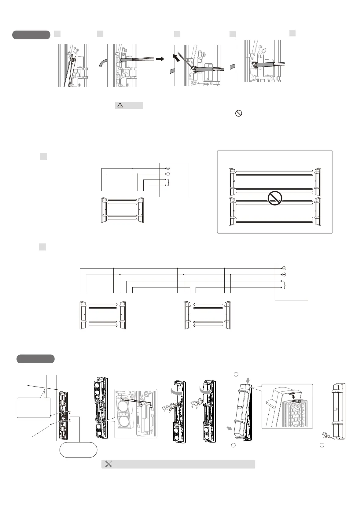
Refer to "Terminal" on the
previous page to make
connections to the terminals
and refer to “Optical alignment”
on the next page to make
alignment for the maximum
level of light reception.
Connect to the terminals
Cut the bush to
the cable size
Run the cable through the bush
Tie the cable
Cut off excess ties
Caution
Do not exceed specifications that may cause fire or damage.
Wiring
1 2
3 4
5
4×20 self tapping
Side wall
Distance from
the side wall:
at least 1 m
83.5 mm
for gang box
Make function settings and optical alignment before mounting the cover.
3
4
1
2
Hook on the upper part of the chassis.
Push the lower part of the cover
until it clicks into position.
1
2
Fasten the cover
lock screw.
3
Mounting
POWER
ALARM
N.C.
(1) (1)(2) (2) (5) (6)
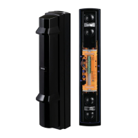
Transmitter Receiver
CONTROL PANEL
< Wiring diagram >
- 2 -
Transmitter Receiver
Note>>
2 Sets stacking installation is not available.
CONTROL PANEL
(1) (1)(2) (2) (1) (2)(5) (6) (1) (2) (5) (6)
2
2 Sets in the line
POWER
TransmitterReceiverTransmitter Receiver
Connect the power supply in parallel. Connect the units serially for a normally closed alarm output and in parallel for a normally open output
(the figure below shows an example for a normally closed alarm output).
ALARM
N.C.
1
1 Set
Connect the power supplies in parallel.
 Loading...