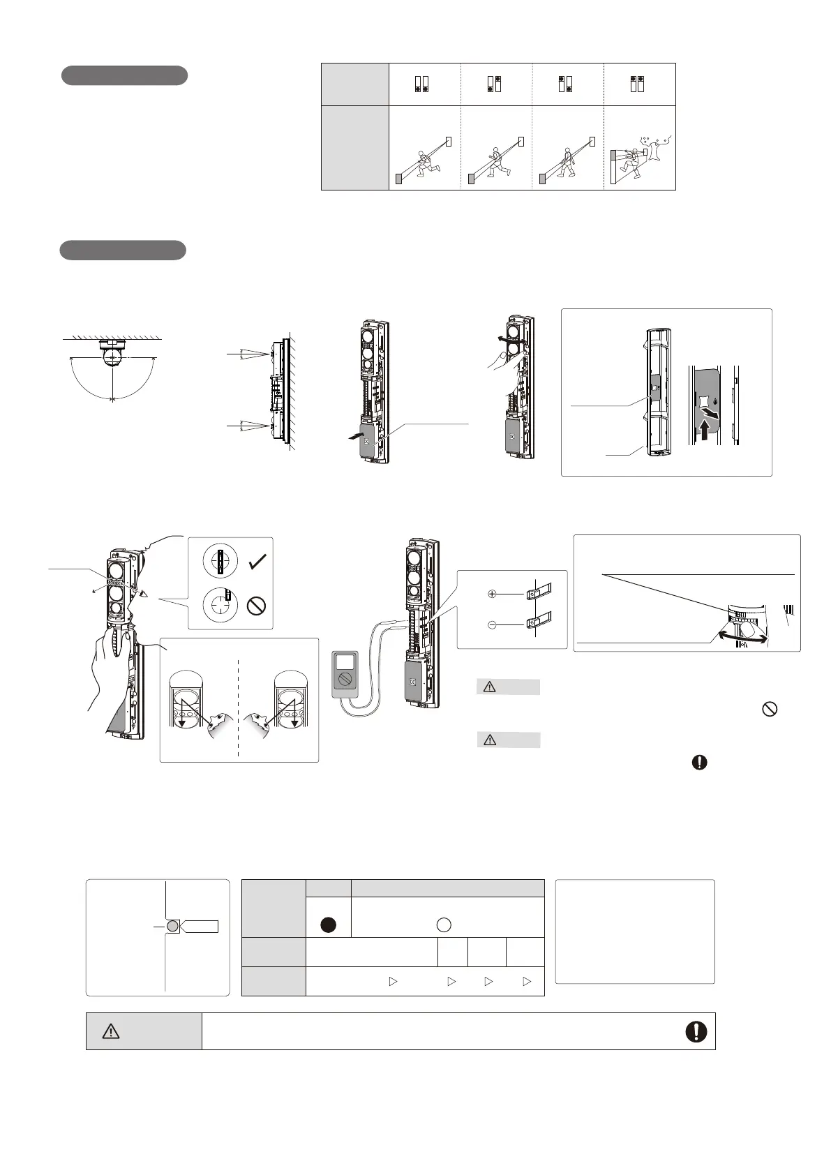
Interruption time
(50 msec)* (100 msec) (250 msec) (500 msec)
Typical
interruption
time setting
Dip switch
(Receiver)
Running Jogging Walking Slow movement
ON
1 2
ON
1 2
ON
1 2
ON
1 2
* For UL/ULC Installations the Setting of 50 msec shall be used.
90°
90°
< Horizontal alignment angle > < Vertical alignment angle >
Cover
10°
10°
10°
10°
[ TOP VIEW ]
[ SIDE VIEW ]
Beam blocking
plate
< Using a beam blocking plate >
Beam blocking
plate
< How to remove >*
* Put it back after aligning for re-using.
Note >>
Optical alignment
Viewfinder
Turn the small dial for horizontal alignment.
Turn the large dial for
vertical alignment.
- Clockwise: Upward
- Counterclockwise: Downward
Do not touch the lens during optical alignment.
Do not look at strong light sources such as sunlight through the
viewfinder.
< How to look into the viewfinder >
Left eye Right eye
From right side From left side
Warning
Caution
< Using a viewfinder > < Using a voltmeter for fine alignment >
Note >>
< LED and monitor jack >
Alarm indicator
LED
Light
interrupted
Light received
Adjustment
level
Monitor jack
output
Realign Fair Good
Excellent
0 V 2.0 V 3.5 V 5.0 V
ON (Red) OFF
Alarm Indicator
LED
Alarm
Receiver
Caution
Be sure to perform fine alignment to ensure the maximum output level through the monitor
jack.
Power indicator LED on the
transmitter is not turned off
when the cover is closed.
( i.e. The tamper button is
depressed.)
Note>>
- 3 -
 Loading...