Connecting Valve Wires to the Sprinkler Timer
• Remove the terminal compartment cover.
• Strip 1/4” (6 mm) of the plastic insulation off the end of
each wire.
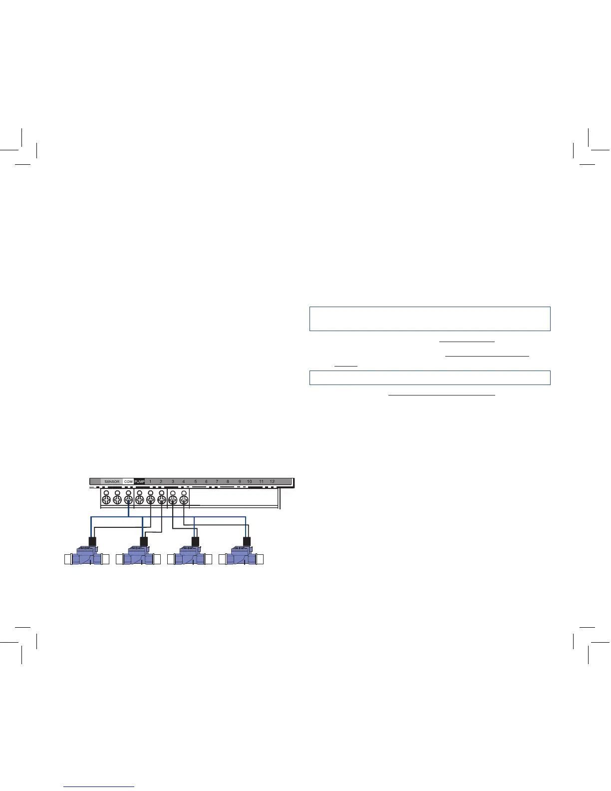
• Determine which valve you want to connect to which station.
• Connect each sprinkler wire (excluding the “Common” wire)
to a separate station terminal (numbered above each terminal
screw) by inserting the bare wire fully into the hole under each
terminal screw. [See Figure 14]
• It may be necessary to open the terminal to allow for wire
insertion or removal. To do this, you’ll need to use a small
Phillips screwdriver.
Note: it isn’t necessary to fully remove the screw
• Connect the common wire to the terminal (white in color)
labeled “COMMON”.
Note: For installation instructions for Pump Start, Master Valve and Rain
Sensors see Appendix A.
5. Connecting Electrical Power
Note: For outdoor installation it is recommended that a qualified electri-
cian completes wiring in accordance with electrical codes and regulation.
This sprinkler timer is intended for use with a Ground Fault Interrupter
(GFI) protected circuit when used outdoors.
Check the model number of your sprinkler timer: various models
are configured differently to meet national requirements. The model
number can be found on the back of the door, together with other
useful information.
FIND YOUR MODEL BELOW AND GO TO THE APPROPRIATE
SECTION:
Models 57880, 57881, 57882, 57883, 27780, 27781, 27782, 27783,
91880, 91881, 91882, 91883
• For Indoor mounting go to the Fitted Line Cord section below.
• For Outdoor mounting go to the Preparing for Permanent
Wiring section below
Models 94880, 94881, 94882, 94883
• Please go to the Preparing for Permanent Wiring section
below.
FITTED LINE CORD INSTALLATION
Replacement of the supply Cord: If the supply cord is damaged it
must be replaced by a service agent or similarly qualified person in
order to avoid a hazard
• Indoor Locations - Insert the line cord into Ground Fault
Interrupter (GFI) outlet.
• Outdoor Locations - Insert the line cord into a power Ground
Fault Interrupter (GFI) outlet connected to a GFI circuit.
PREPARING FOR PERMANENT WIRING
The following three “Pigtail” wires extend out of the bottom of the
box:
• Black “pigtail” wire – Hot
• White “pigtail” wire – Neutral
• Green “pigtail” wire –Ground
Figure 14: Connecting Sprinkler Wire
 Loading...