2 Operating a motor
1
2
3
4
•
Single-phase 100-120 VAC
•
Single-phase 200-240 VAC
•
Three-phase 200-240 VAC
Protective Earth
Terminal
Refer to "5 Connection"
Refer to "6 Operating by front panel"
Protective Earth Terminal
1 Connecting
OPERATING MANUAL OPERATING MANUAL
1
2
3
Connector
cap
Remove
Attach
Secure
Be sure to turn down the locking lever
till the position shown in the gure.
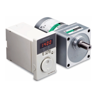
Motor
Driver
PE
To power
supply
10 mm
(0.39 in.)
PE
FWD
REV
Lead wire
Screwdriver
Be sure to ground using the
Protective Earth Terminal .
Protective Earth
Terminal
Connect a power supply cable according to the power-supply
voltage specications of the driver. Prepare the power supply cable
since it is not supplied with the product.
Be sure to ground the product. Failure to do so may result in electric shock or damage to the product.
Static electricity may cause damage to the product if the Protective Earth Terminals are not grounded.
Note
Prepare a grounding wire since
it is not supplied with the product.
AWG18 to 14
(0.75 to 2.0 mm )
2
M4
AC power ON
Rotation direction selection
Decelerate
Connection cable
The gure is an example for
when the product is of a
single-phase 100 VAC.
If the power supply is turned on while the operation switch
is set to the RUN side, the alarm is generated.
【
How to reset
】
Set the operation switch to [STAND-BY].
The alarm is reset, and the motor rotation
speed is displayed.
P
U
S
H
-
S
E
T
FWD
REV
Rotation speed
0 r/min (standstill)
Accelerate
[ Example: 50
→
1000 r/min ]
CN2
CN3
CN1 CN1
CN1
The motor rotates.
50 r/min (factory setting)
The gures show the round shaft type.
With the combination type, the gearhead output
shaft rotates in the opposite direction to the above
gure when the gear ratio is 30, 50, and 100.
When the setting dial is
pressed, the display
changes to lighting
from blinking, and the
speed will be set.
When you start the
motor next time, it will
rotate at the set speed.
CN1
Setting dial
Press
When the setting dial is turned, the display blinks.
You can change the speed while blinking.
Operation
switch
Set the operation switch to
Set the operation switch to
Rotation
direction switch
Select the motor rotation direction using the rotation direction switch.
[ STAND-BY ]
Power ON The display blinks
Ground
FWD
REV
Insert into CN1
AWG18 to 14 (0.75 to 2.0 mm )
2
Start of motor
Change of motor speed
Set
Adjustment
[ RUN ]
FWD
REV
The motor stops.
To stop the motor
Set the operation switch to
[ STAND-BY ]
Connection for motor and cable
This is an example for when the cable is "leading
in direction of output shaft." In the case of the
cable of "leading in opposite direction of output
shaft," the cable leading direction is opposite in
and .
2
3
Keep the locking
lever in the position
shown in the gure, and insert.
Position of lever
Locking
lever
 Loading...