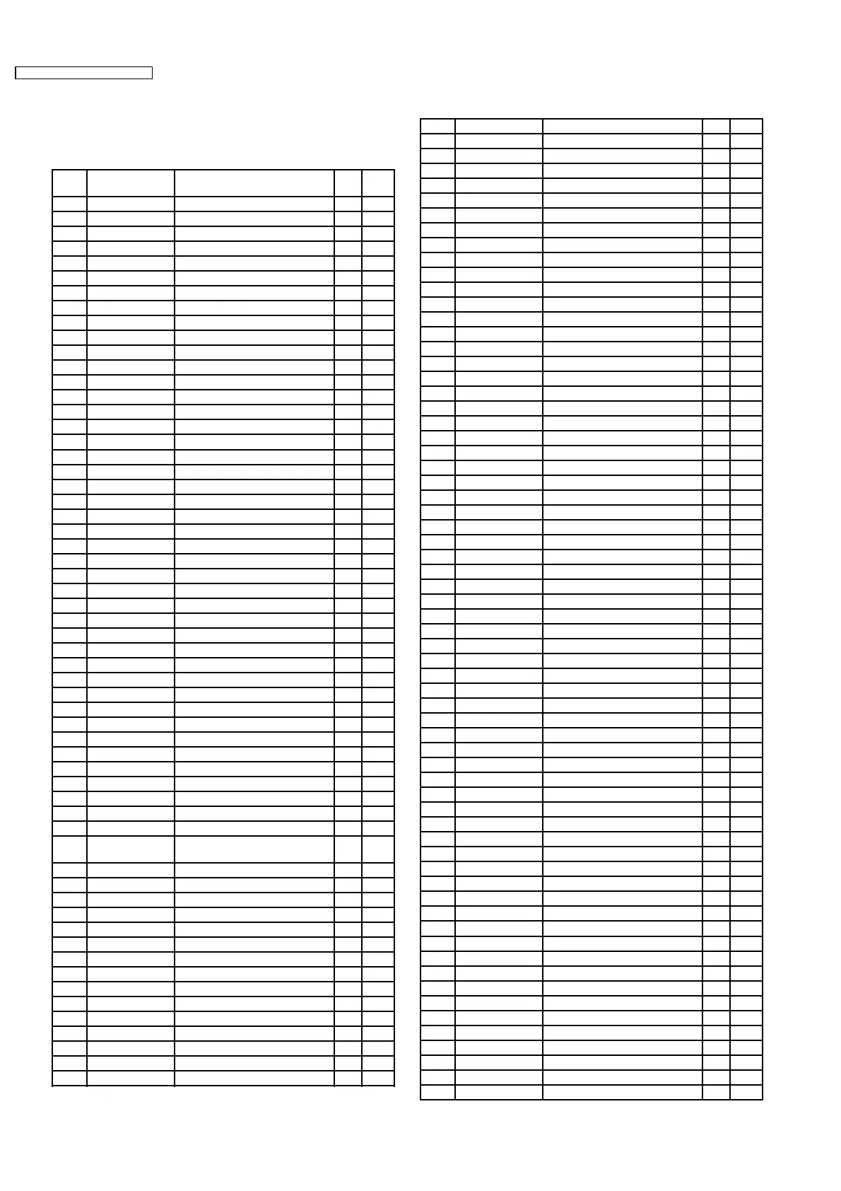
9.1. Main Block
IC621 : C2CBKJ000009
Pin
No.
Port Description I/O (V)
1 MD1 (Connecting to VDD) - 5.2
2 MD2 MPU mode setting I 4.4
3 NC No connector - -
4 NC No connector - -
5 CD RESET CD reset O 5.1
6 CD ON CD controller enable O 5.1
7 TIM-SP TIM O 0
8 TIM-ST TIM strobe O 0
9 VSS Ground - 0
10 TIM-REC/PLAY TIM recode/play O 0
11 VCC +3V power supply - 3.0
12 PLL CE PLL chip enable O 0
13 PLL CLK PLL clock O 0
14 PLL DI PLL data O 0
15 VSS Ground - 0
16 PLL DO PLL data I 4.9
17 PVCC1 +5V power supply - 5.2
18 NC No connector - -
19 DSP-SI DSP serial data O 0
20 DSP-CLK DSP Clock for serial data O 5.2
21 DSP-RST DSP reset O 0
22 DSP-WRQ DSP data write request O 0
23 DSP-WRDY DSP write ready I 0
24 DSP-CS DSC chip select O 5.1
25 6.5V-DET 6.5V detection I 5.2
26 FLASH-TXD2 Not used - -
27 FLASH-RXD2 Not used - -
28 AF-MUTE Audio mute control O 5.1
29 VSS Ground - 0
30 MUTE1 Mute control O 5.1
31 MUTE2 Mute control O 5.1
32 F.IN Tape loading motor control O 0
33 R.IN Tape loading motor control O 0
34 CAN-IRQ CAN BUS request I 5.2
35 NC No connector - -
36 NC No connector - -
37 R.CONT Radio power control - 5.1
38 ILL1 Illumination signal I 2.5
39 IF CONT IF counter O 5.1
40 CLK Clock for the second display O 0
41 DATA Data for the second display O 0
42 ENA-IN Enable for the second display I 0
43 ENA-OUT Enable for the second display O 5.1
44 E2-CLK Clock for security EEPROM
data
O 0
45 E2-DI Security EEPROM data O 0
46 E2-DO Security EEPROM data I 0
47 E2-CE Security EEPROM enable O 0
48 VSS Ground - 0
49 AMP+ Ext. Amp. control O 5.1
50 PVCC1 +5V power supply - 5.2
51 CLK Clock for power control IC O 0
52 DATA Data for power control IC O 0
53 LATCH Data latch O 5.1
54 STBY Power control IC standby O 5.1
55 COM-CNT +10V power switch O 5.1
56 MSOUT Tape MS detection I 3.9
57 T.LOAD Tape loading I 4.7
58 A/B Tape side detection I 0
59 T.IN Tape insert detection I 4.7
60 PVCC2 +5V power supply - 5.2
61 +B DET Battery level detection I 4.8
62 VSS Ground - 0
63 CD REMO CD CH remocon data O 5.1
64 CD DATA CD CH data I 0
65 CD CLK CD CH clock I 0
66 CAN-TDO CAN BUS data I 0
67 VSS Ground - 0
68 VSS Ground - 0
69 CAN-RDI CAN BUS data O 4.8
70 S.CONT Key status signal I 5.2
71 P-ON SW Power on SW I 4.7
72 P-SI Serial data for panel O 5.1
73 P-SO Serial data for panel I 0
74 P-CLK Clock for panel O 5.1
75 NC No connector - -
76 PLL VCC PLL power supply I 3.0
77 PLL CAP Filter for PLL Vcc - 1.5
78 PLL VSS Ground - 0
79 RES Reset I 4.7
80 MNI (Connecting to VCC) - 5.2
81 STBY Power control IC standby O 5.2
82 FWE (Ground pull-down) - 0
83 XTAL Crystal oscillator - 2.1
84 VCC +3V power supply - 3.0
85 XTAL Crystal oscillator - 1.7
86 VSS Ground - 0
87 OSC1 (Connecting to Vcc) - 3.0
88 OSC2 Not used - -
89 PVCC1 +5V power supply - 5.2
90 ILL2 Illumination signal I 0
91 VSS Ground - 0
92 PANEL RESET Reset output O 5.2
93 CAN RESET CAN BUS reset O 4.8
94 GALA GALA input I 0
95 CONT Control signal detection I 4.7
96 S.REMOCON Remocon data I 5.1
97 ANT CNT2 Motor antenna control O 5.0
98 R CLK Clock for RDS data I 2.5
99 NC No connector - -
100 NC No connector - -
101 AVCC +5V power supply - 5.2
102 VREF Reference voltage terminal - 5.2
103 VCONT AM/FM level detection I 0
104 MP Multi-path detection I 0
105 NOISE FM noise level detection I 1.7
106 DSP-MON (+5V pull-up) I 4.4
107 IGN IGN signal input I 5.2
108 T.MUTE Telephone mute I 4.7
109 N. CONT Navi control I 4.7
110 R DATA RDS data I 2.5
111 CD-EJECT CD eject SW I 4.7
112 E-A Tape end detection I 0
113 E-B Tape end detection I 0
114 EQ Metal tape detection I 0
115 Bit 3 Tape mode SW I 0
116 Bit 2 Tape mode SW I 0
117 Bit 1 Tape mode SW I 0
118 TA.MON TA monitor I 0
119 AVSS Ground - 0
120 TIM-CA0 TIM phrase setting O 0
121 TIM-CA1 TIM phrase setting O 0
122 TIM-CA2 TIM phrase setting O 0
123 TIM-CA3 TIM phrase setting O 0
124 TIM-DEL TIM delete O 5.1
125 CD SCKM CD serial clock I 0
9 TERMINALS DESCRIPTION
8
AUDI / CQ-JA1920L / CQ-JA1924L
 Loading...