12.1. Indoor Electronic Controllers
Removal Procedures
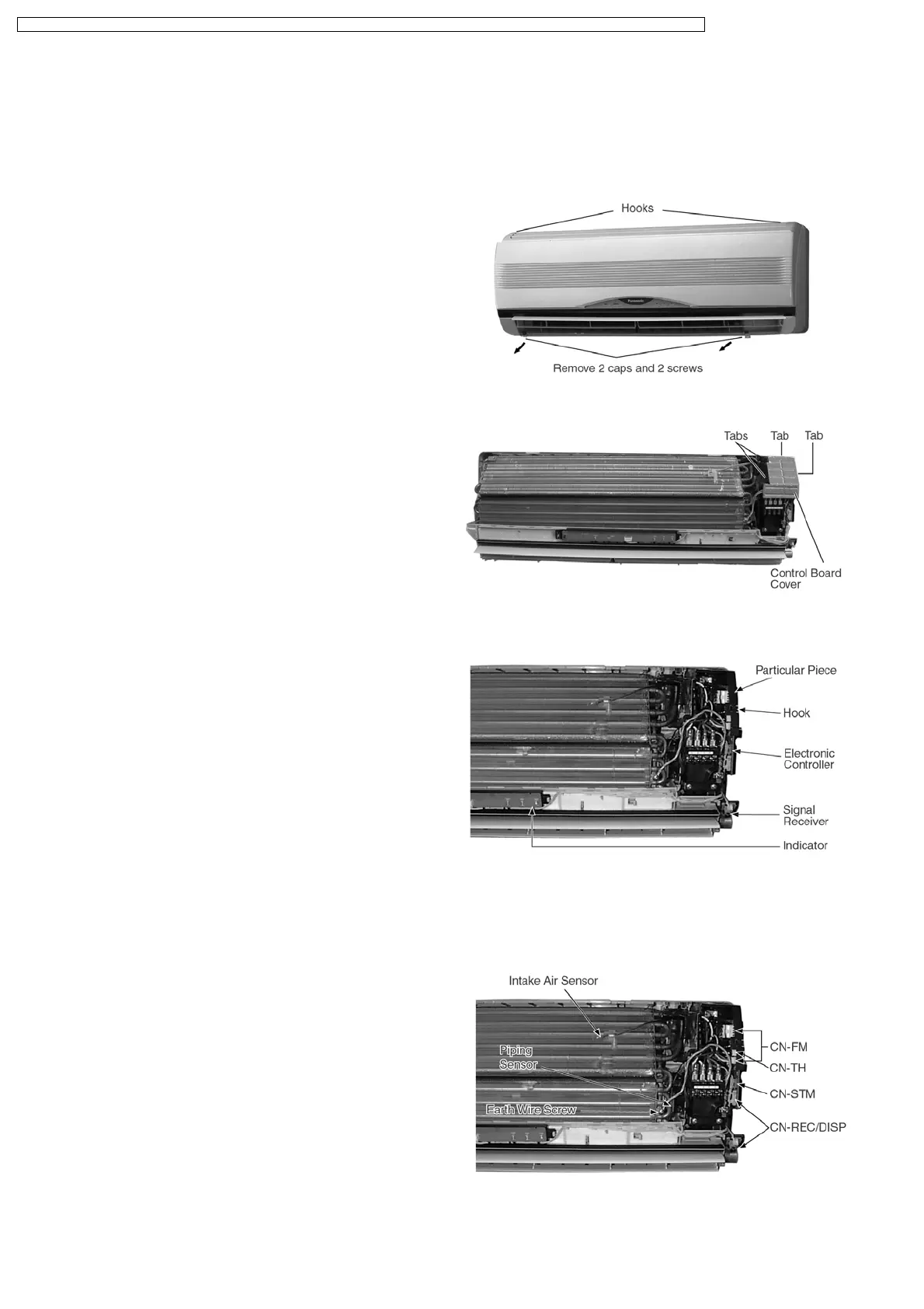
1. The Electronic Controller, a Signal Receiver and an
Indicator (Fig. 3) can be seen by the below steps:
• Remove the 2 caps and 2 screws at the bottom of the
Front Grille. (Fig. 1)
• Remove the Front Grille by releasing the 2 hooks at the
top of the Front Grille. (Fig. 1)
• Remove the Control Board Cover by releasing the 2
tabs at left, 1 tab on top and 1 tab at right side of the
Control Board Cover. (Fig. 2)
2. To remove the Electronic Controller:
• Release the Particular Piece. (Fig. 3)
• Release the hook that hold the Electronic Controller.
(Fig. 3)
12.2. Indoor Fan Motor and Cross
Flow Fan Removal Procedures
• Remove the Control Board by:-
− Releasing CN-REC/DISP connectors. (Fig. 4)
− Releasing CN-FM connectors. (Fig. 4)
− Releasing CN-STM connector. (Fig. 4)
− Removing the Earth Wire screw. (Fig. 4)
− Releasing the Intake Air Sensor. (Fig. 4)
− Releasing the Piping Sensor. (Fig. 4)
Fig. 1
Fig. 2
Fig. 3
Fig. 4
12 Servicing Information
62
CS-A7BKP CU-A7BKP5 / CS-A7BKP CU-A7BKP6 / CS-A9BKP CU-A9BKP5 / CS-A9BKP CU-A9BKP6 / CS-A12BKP CU-A12BKP5 / CS-A12BKP CU-A12BKP6
 Loading...