-
9
--
8
-
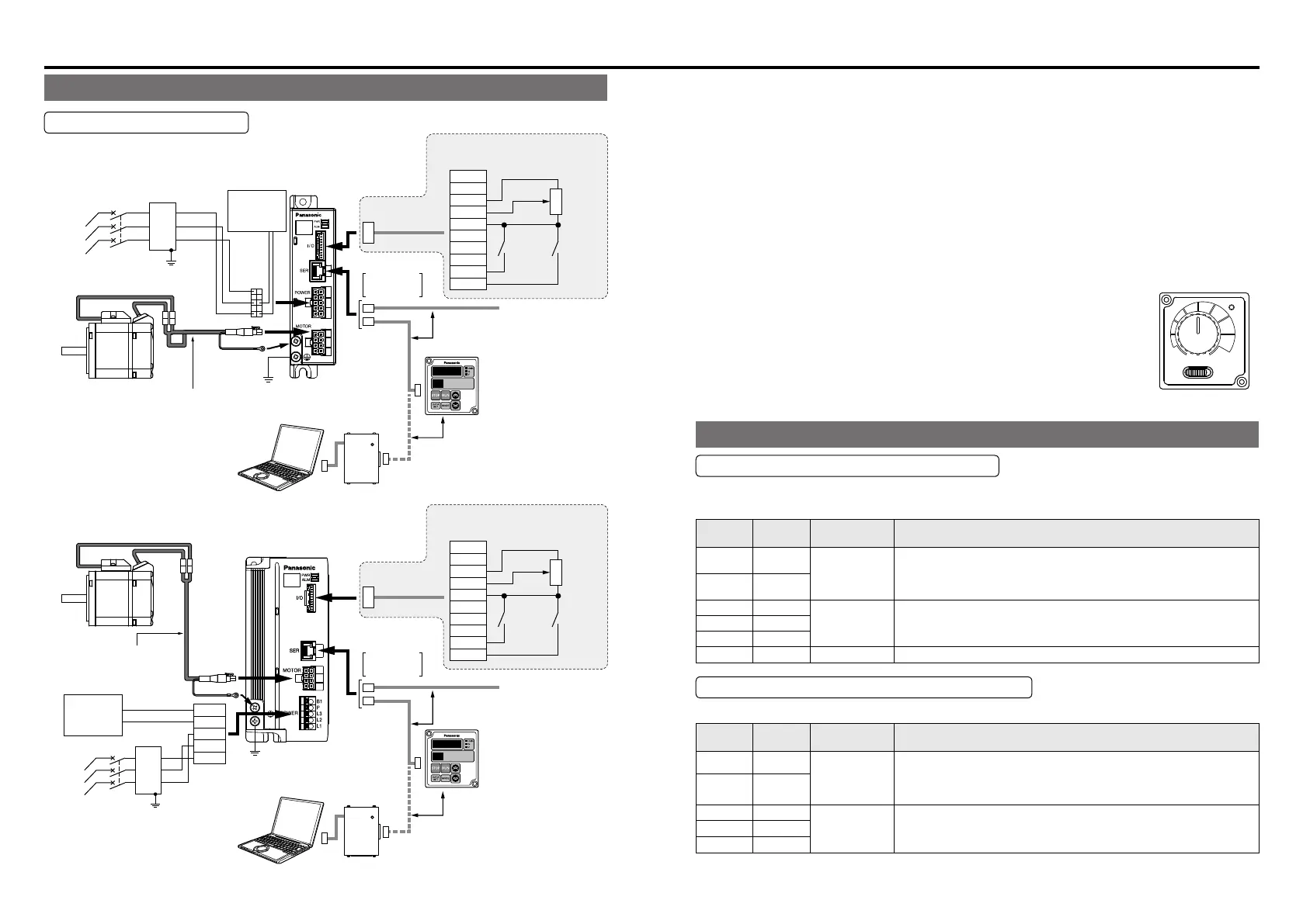
System conguration and wiring
System conguration/ general wiring diagram
Standard wiring diagram
• In Case of 3-Phase 200 V (50 W, 100 W)
Personal computer
(Customer preparation)
Personal computer (Customer preparation)
* When you use single phase,
connect the main power
between L1 and L2 terminals.
02
for control
signals (I/O)
* 1
* 1
External speed setting
Variable resister 5 kΩ
B characteristic 1/4 W
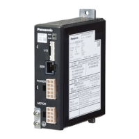
Brushless
amplifier
change of
Direction
Run/Stop
command
10
1
01
+5V
FIN
GND
I3
I4
I5
I2
I1
Power
supply
input
L1
L2
L3
1
5
6
10
MCCB
Molded Case
(
Circuit Breaker
)
02
Connector
for control
signals (I/O)
External speed setting
Variable resister 5 kΩ
B characteristic 1/4 W
Brushless amplifier
change of
Direction
Run/Stop
command
10
1
01
+5V
FIN
GND
I3
I4
I5
I2
I1
• In Case of 3-Phase 200 V (200 W, 400 W, 750 W)
Power
supply
input
L1
L2
L3
MCCB
Molded Case
(
Circuit Breaker
)
Grounding
B1
P
L3
L2
L1
* When you use single phase,
connect the main power
between L1 and L2 terminals.
Grounding
RS485
Digital key pad
connecting
cable
(option)
Digital key pad
connecting
cable (option)
Connector
for (SER).
It cannot be used simultaneously.
It cannot be used simultaneously.
Digital key pad
(Option)
digital display console.
It enables change of
parameter.
refer to the Operating
(
Instructions (Overall).
)
PC connecting cable (option)
POWER
It cannot be used
simultaneously.
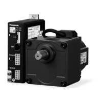
Motor extension cable (option)
Select if needed (to 10 m).
Motor extension cable
(option)
Select if needed (to 10 m).
RS485
Digital key pad
(Option)
digital display console.
It enables change of
parameter.
refer to the Operating
(
Instructions (Overall).
)
PC connecting cable (option)
POWER
It cannot be used
simultaneously.
Be sure to ground
the grounding terminal.
Be sure to ground
the grounding terminal.
External
regenerative
resistor
(option)
External
regenerative
resistor
(option)
Noise
filter
Noise
filter
Connector
for (SER).
Wiring
• In wiring to power supply (outside of equipment) from MCCB, use an electric wire of 1.6 mm
diameter (2.0 mm
2
) or more both for main circuit and grounding.
Apply grounding class D (100 Ω or below) for grounding.
Do not tighten the ground wires together, but connect them individually.
Fastening torque of earth screws to be 0.49 to 0.98 N·m.
• For details of parameters, refer to the Instruction Manual (Overall).
• For the wiring of communication connector (SER), see P10.
• When a personal computer is connected, please use communicating software "PANATERM
for BL" (it is gratis download from URL).
Change of parameter and the monitor of operational status can be performed.
If your PC does not have RS232 port, use RS232-USB converter.
*1 You can use the Console A(option) and a Console A connecting cable
(option) for connection with the Connector for control signals (I/O)
LOW
STOP
HIGH
RUN
Console A
(option)
Function of terminal
Connector for power supply (POWER)
• 50 W, 100 W
Connector on Amplier Side: Part No. 5569-10A1-210 (Molex Inc.) or equivalent
Terminal
number
Terminal
Symbol
Terminal
name
Terminal explanation
3 B
terminal for
Regenerative
resistor
Please connect Regenerative resistor of an option if needed.
Regenerative resistor name:
100 V type DV0P2890 (50 Ω)
200 V type DV0PM20068 (200 Ω)
5 P
6 L3
Terminal for
Power supply
input
Connect the terminal to commercial power supply conforming to
voltage specication. When you use single phase, connect the main
power between L1 and L2 terminals.
8 L2
10 L1
1,2,4,7,9 NC
-
Do not connect anything to NC.
Terminal for power supply input (POWER)
• 200 W, 400 W, 750 W
Terminal
number
Terminal
Symbol
Terminal
name
Terminal explanation
5 B1
terminal for
Regenerative
resistor
Please connect Regenerative resistor of an option if needed.
Regenerative resistor name:
100 V type DV0P2890 (50 Ω)
200 V type DV0PM20068 (200 Ω)
4 P
3 L3
Terminal for
Power supply
input
Connect the terminal to commercial power supply conforming to
voltage specication. When you use single phase, connect the main
power between L1 and L2 terminals.
2 L2
1 L1
Recommended Pin Terminal: NICHIFU TERMINAL Ind. TGN TC-1.25-11T
 Loading...