Do you have a question about the Panasonic SA-AK18 and is the answer not in the manual?
| Type | Stereo System |
|---|---|
| Speaker Configuration | 2.0 |
| Speakers | 2 speakers |
| CD Player | Yes |
| Tuner Bands | FM/AM |
| Bluetooth | No |
| USB Port | No |
| Inputs | AUX |
| Frequency Response | 20 Hz - 20 kHz |
Details specifications for the amplifier section.
Details specifications for the cassette deck section.
Details specifications for the CD section.
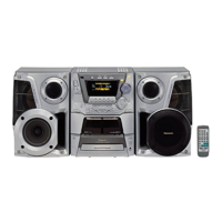
Lists the remote control transmitter as an accessory.
Precautions for handling the traverse deck and optical pickup.
Steps to prevent electrostatic breakdown when handling electronic components.
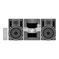
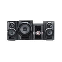
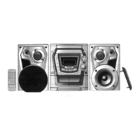
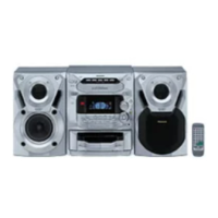
Identifies and describes the controls on the front panel of the unit.
Identifies and describes the buttons on the remote control.
Specific steps for checking the main, panel, deck, and power PCBs.
Step-by-step guide for replacing the traverse deck unit.
Detailed steps for disassembling and assembling the traverse unit.
Step-by-step instructions for disassembling and assembling the disc tray mechanism.
Explains the self-diagnostic function and error code display.
Instructions on how to access the self-diagnostic mode.
Lists error codes and conditions for the cassette mechanism.
Lists error codes and conditions for the CD/Changer mechanism.
Instructions on how to activate the CD test mode.
Procedures for measurements and adjustments on the cassette deck.
Steps for adjusting the head azimuth on cassette deck 1 and 2.
How to check bias and erase voltages for the cassette deck.
Steps for aligning the AM Intermediate Frequency (IF) circuit.
Details the terminal functions of IC701, the servo amplifier.
Explains the terminal functions of IC702, the servo processor and D/A converter.
Details the terminal functions of IC703, the motor driver IC.
Presents the overall block diagram of the system.
Main circuit schematic diagram showing component interconnections.
Schematic diagram for the deck circuit, detailing its components.
Schematic diagram for the panel circuit, showing front panel connections.
Schematic diagram for the CD servo printed circuit board.
Illustrates the location of parts for the deck mechanism.
Lists all parts for the deck mechanism with reference numbers.
Illustrates the location of parts for the CD loading mechanism.
Lists all parts for the CD loading mechanism with reference numbers.
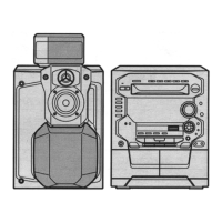
Illustrates the location of cabinet parts and chassis components.
Lists all parts related to the cabinet and chassis of the unit.
Lists printed circuit boards and their part numbers.
Lists integrated circuits with part numbers and functions.
Lists transistors with part numbers and functions.
Lists all switches and their functions.
Lists all connectors and their pin assignments.
Lists coils and transformers with part numbers.
Lists relays used in the unit.
Lists oscillators and their specifications.
Lists various jacks like antenna and RCA connectors.
Lists different types of wires and cables used in the unit.
Schematic for the AC transformer circuit for E/EG regions.
Schematic for the AC transformer circuit for EB region.
Schematic for the sub-transformer circuit.
Details the terminal functions of IC701, the servo amplifier.
Explains the terminal functions of IC702, the servo processor and D/A converter.
Details the terminal functions of IC703, the motor driver IC.
Explains the terminal functions of IC600, the system microprocessor.
Details the terminal functions of IC500, the power IC.
Explains the terminal functions of IC501, the voltage regulator.
Details the terminal functions of IC1, the motor drive IC.
Explains the terminal functions of IC102, the PLL frequency synthesizer.
Details the terminal functions of IC101, the IF amplifier.
Schematic for the AC transformer circuit for E/EG regions.
Schematic for the sub-transformer circuit.
Schematic diagram of the power supply circuit.
Schematic diagram for the first tact switch circuit.
Schematic diagram for the panel circuit, showing front panel connections.
Schematic diagram for the second tact switch circuit.