For Technical Support: www.panduit.com/resources/install_maintain.asp
INSTALLATION INSTRUCTIONS
© Panduit Corp. 2016
V00029KB
Page 2 of 6
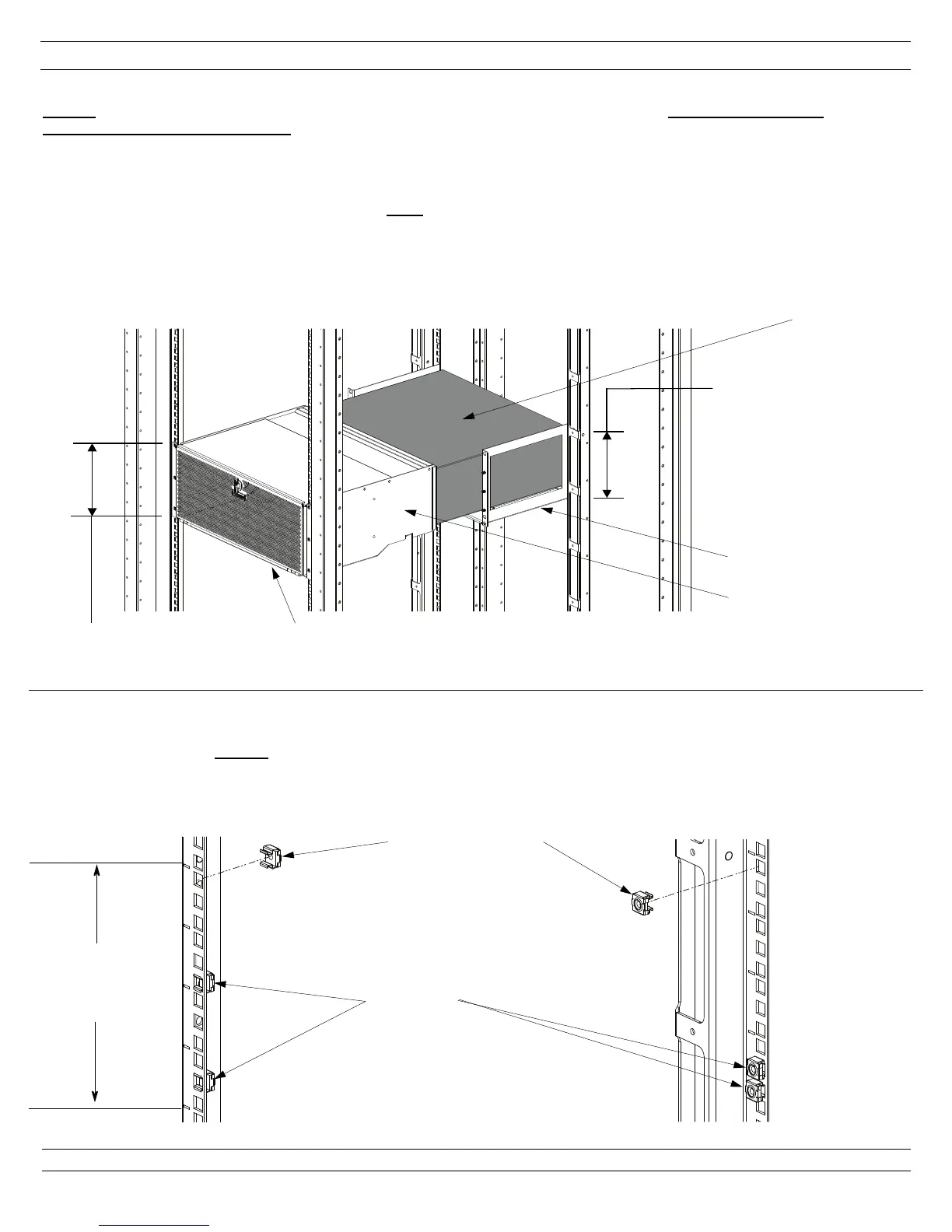
Determine Location of Switch Ducting and Switch Support Bracket
NOTES: Front to back span of equipment rails may need to be adjusted to accomodate your switch. Front to rear rail spacing
requirements range from 24.0" TO 30.5". Equipment installed directly below CDE3 may impede routing of switch power cord if installed
prior to CDE3.
Switch Ducting and Switch Support Bracket components of CDE3 require (4) rack spaces for installation. Switch Ducting and Switch Sup-
port Bracket are to be installed at the same vertical rack position. CDE3 components are to be installed prior to switch installation and are
designed to support the switch. (CDE3 ducting system
ONLY requires use of primary Cisco rack mount brackets. Cisco supplied switch
cradle or extension brackets are not compatible with CDE3.)
Grounding Cage Nut
(green)
Cage Nut
(installed)
Intended
Mounting
Location
(4 rack spaces)
3 RU Switch
(reference; port side of
switch faces Hot Aisle)
Install Cage Nuts
Insert (3) cage nuts per Front and Rear equipment rail at CDE3 component mounting locations (12 total cage nuts are to be installed). (1)
grounding cage nut (green)
must be installed in (1) Front and (1) Rear equipment rail opposite each other on Left or Right Hand side. The
view below depicts cage nut locations for front and rear equipment rails on Left Hand Side of Cabinet
Switch Ducting
Switch Support Bracket
Intended
Mounting
Location
(4 rack spaces)
Intended Mounting Location
(4 rack spaces)
Perforated Door of Switch Ducting
(faces Cold Aisle)
FRONT OF
CABINET
REAR OF
CABINET
FRONT OF
CABINET
REAR OF
CABINET
 Loading...